– 3 –
Care must be taken to insure an adequate air supply for the wa ter heater.
A. Install equipment only where the water heater will have sat is fac tory com bus tion, proper vent ing,
and the maintenance of temperature at safe limits all around the unit under normal operating con-
ditions. Free circulation of air around the water heater is essential. If the air supply is inadequate,
introduce outside ai
r. Any temperature above 90
°
F around the heater indicates a need for addi-
tional air (see NFPA 31 for air requirements).
B. In a
ddition to air needed for combustion, air may be required for draft control; cooling off; con trol ling
dew point; heating; drying; oxi da tion or dilution; safety ex haust; odor control; and compressors.
C. Make sure air around the water heater is adequate for personnel comfort and working conditions.
D
. Check for proper draft. Place a draft gauge in the chimney above the draft diverter. Drafts should
be at least -0.02" W. C. and less than -0.05” W.C. while the water heater is in operation.
Unconfined space: No additional combustion and ven ti la tion air is required if the volume of the
space is greater than 50 cubic feet per 1,000 BTUH of the combined total input of all equipment in -
stalled
in that space. Rooms leading directly to the space through openings which cannot be closed
are considered part of the unconfined space.
Confined space: When the unit will be installed in a space with a volume of less than 50 cubic feet
per 1,000 BTUH, the space must be vented at the floor for combustion air and at the ceiling for ven -
ti la tion. This air can be supplied from either inside or outside of the building as conditions allow (refer
to
NFPA 31 or local codes).
A. Inside air supply: Provide two permanent openings; one within 12" of the top of the enclosure and
one within 12" of the bottom, leading directly to room(s) of sufficient vol ume so that the combined
volume of all the space meets the criteria for unconfined space. Each opening requires a mini-
mum free area of one (1) square inch (two square inches total) per 1,000 BTUH of the combined
total input of all equip ment installed in the enclosure, but not less than 100 square inches.
B. Outside
air supply: Provide two permanent openings; one within 12" of the top of the enclosure
and one within 12" of the bottom. These openings must lead directly to crawl and attic spaces
leading directly to the outside of the building.
1.
Leading directly to outside or through vertical ducts: Each opening (top and bottom)
requires a minimum free area of one (1) square inch (two square inches total) per 4,000 BTUH
of the combined total input of all equipment in stalled in the enclosure.
2. Leading to the outside through horizontal ducts:
Each opening (top and bottom) requires a minimum free
area of one (1) square inch (two square inches total) per
2,000
BTUH of the combined total input of all equipment
installed in the enclosure.
Louvers and grilles: In calculating the “free” area in Equip -
ment Located in Confined Spaces, consider the blocking
effects of louvers, grilles, or screens pro tect ing openings. The
screens cannot be smaller than one (1) inch of mesh. If the “free”
area of a louver or grille is known, it should be used in calculat-
ing
the size opening required to provide the “free” area specified.
If the design and “free” area is not known, assume wood louvers
have 20% to 25% “free” area, and metal louvers and grilles 60%
to 75%. Fix louvers and grilles in the open position or interlock
with the equipment so they are opening automatically during
equipment operation.
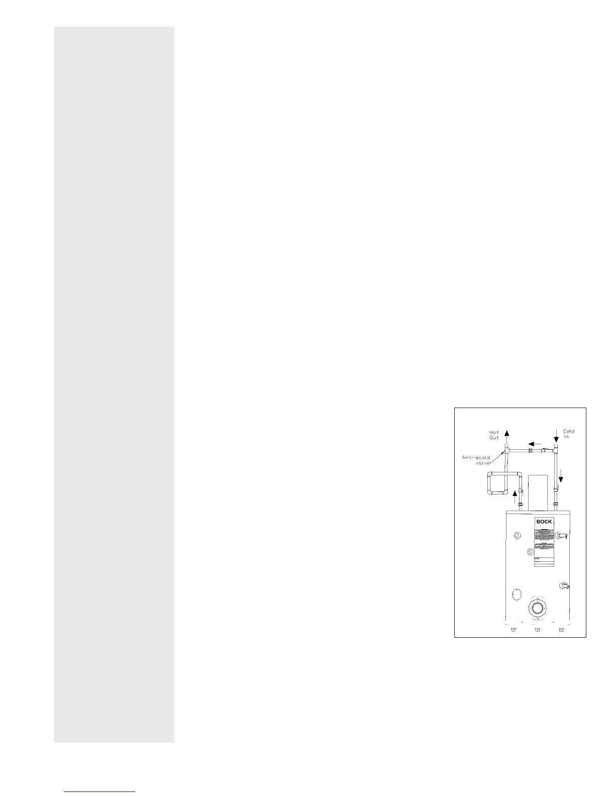
Models 72E and 361E have dip tubes. When using sweat fit tings,
do
not apply heat to the nipples. Pipe hot and cold lines with a
union and valve on each line.
If backflow preventers and pressure regulators are installed or if
the heater is installed in a closed system, allow for water expan-
sion by installing either a thermal expansion valve or an ex pan sion tank in the system. Contact the
local water sup pli er or plumbing in spec tor to correct the situation.
Piping
components and connection materials (eg, solder, solvent cement, thread joint compounds)
used in space heating systems and connected to the service water heater shall be suitable for
use with potable water. Toxic chemicals such as those used for boiler treatment shall not be intro-
duced into the potable water system that is also used for space heating. A water heater that will
be
used to supply domestic hot water shall not be connected to the heating system or connected
with components previously used with a non-potable water heating appliance.
COMBUSTION &
VENTILATION AIR
NOTE: All ducts
must have the same
cross sectional area
as the free area of
each opening to
which they connect.
The minimum side
dimension of a rec -
tan gu lar duct must
be no smaller than
three (3) inches.
Caution:
Operation
of exhaust fans, ven-
tilating sys tems,
power burn ers, in -
duced draft systems,
clothes dryers, or
fire places may cre-
ate con di tions that
require special
attention to avoid
un sat is fac to ry op er -
a tion of installed
equipment.
WATER PIPING
FIGURE 1
 Loading...