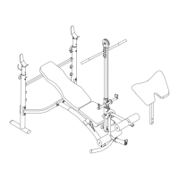
BCB 810 Mid-Width Bench
Assembly Instructions
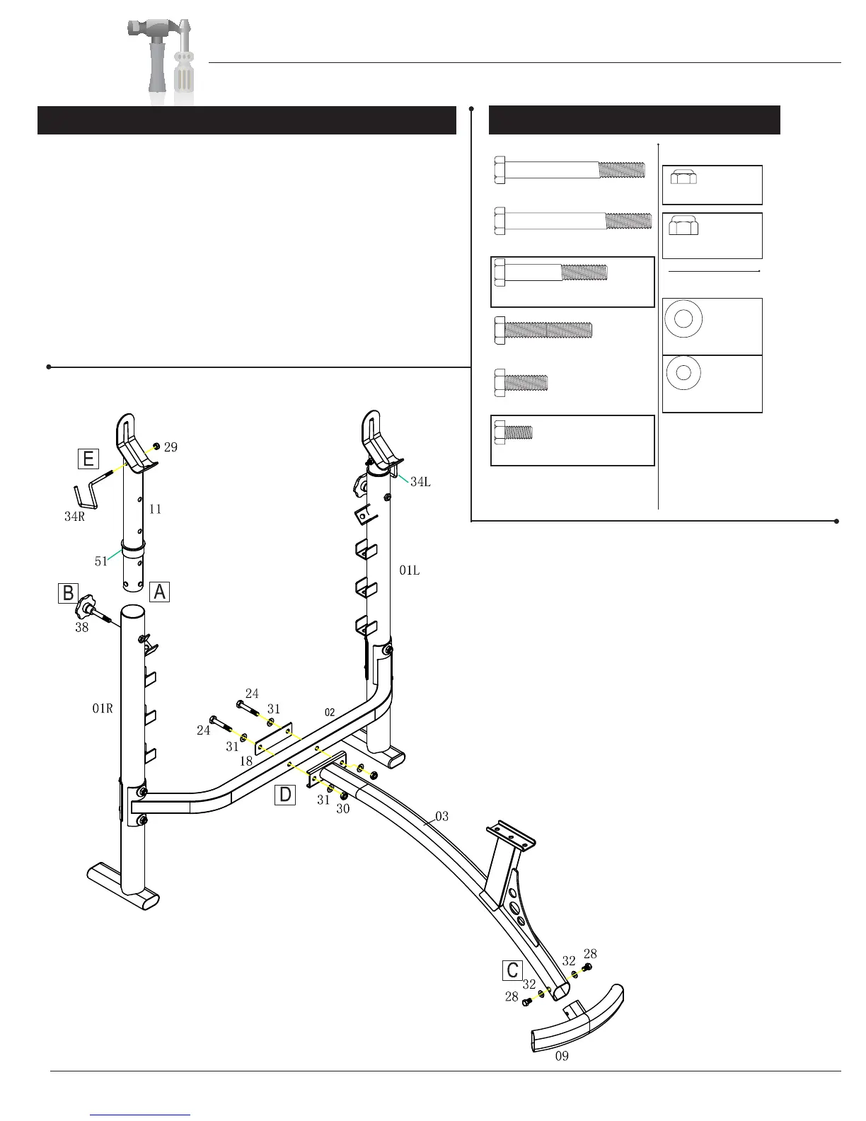
A. Insert one Crutch Tip (#11) into each of the two Upright
Assemblies (#01R & #01L), push the Round Open End Plugs
(#51) into the Upright Assemblies (#01R & 01L).
B. Select the desired height of both Crutch Tips (#11) and then
secure each one by screwing one Knob Bolt (#38) through the
rear of each Upright Assembly (#01R & #01L) and then through
the Crutch Tip (#11).
C. Attach the Front Stabilizer (#09) to the Main Frame (#03)
using
two Hex Bolts (#28) and two Washers (#32).
A s s e m b l y S t e p 2
Hardware Required
Page 6
Please note: This
diagram is designed to
help you easily identify
the hardware type and
quantity you will need
to complete each step.
#24 Hex Bolt (M10x60 mm)
[2 Pieces]
#26 Hex Bolt (M10x50 mm)
#27 Hex Bolt (M10x25 mm)
#28 Hex Bolt (M8x15 mm)
[2 Pieces]
Bolts Nuts
Washers
#22 Hex Bolt (M10x80 mm) #29 Lock Nut (M6)
[2 Pieces]
#30 Lock Nut (M10)
[2 Pieces]
#31 Washer (M10)
[4 Pieces]
#32 Washer (M8)
[2 Pieces]
#23 Hex Bolt (M10x85 mm)
D. Align the Main Frame (#03) to the Rear Cross Brace
(#02). Slide two Hex Bolts (#24) through two Washers
(#31) and one Flat Reinforcement Plate (#31). Continue
to push these two bolts through the Rear Cross Brace
(#02) and then through the Main Frame (#03). Secure
this assembly using two Washers (#31) and two Lock
Nuts (#30).
E. Insert the Safety Hooks (#34L) & (#34R) into the holes
on top of both Crutch Tips (#11). Secure them with two
Lock Nuts (#29).