BCB 810 Mid-Width Bench
Assembly Instructions
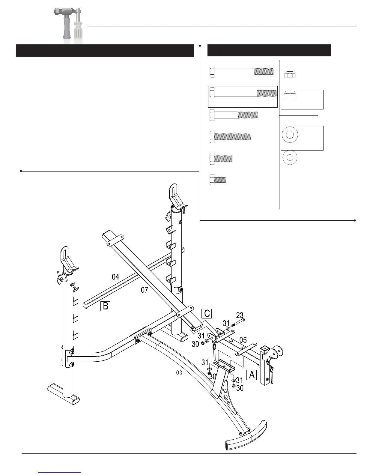
A. Align the two bolts protruding from the bottom of the Front
Upright (#05) to the two holes located on the piece that extends
upward from the Main Frame (#03). Secure the Front Upright (#05)
to the Main Frame (#03) using two Washers (#31) and two Lock
Nuts (30).
B. Slide the Backrest Adjustment Bar (#04) into the highest pair
of U-shaped brackets, which are located on the inner side of
the two Upright Assemblies (#01R & #01L). Note this bar can be
positioned into any of the three U-shaped brackets to adjust the
incline of the Backrest Frame (#07).
C
Attach the Back Rest Frame (#07) to the Front Upright (#05) using
one Hex Bolt (#23) two Washers (#31) and one Lock Nut (#30).
A s s e m b l y S t e p 3
Hardware Required
Page 7
Please note: This
diagram is designed to
help you easily identify
the hardware type and
quantity you will need
to complete each step.
#24 Hex Bolt (M10x60 mm)
#26 Hex Bolt (M10x50 mm)
#27 Hex Bolt (M10x25 mm)
#28 Hex Bolt (M8x15 mm)
Bolts Nuts
Washers
#22 Hex Bolt (M10x80 mm) #29 Lock Nut (M6)
#31 Washer (M10)
[4 Pieces]
#32 Washer (M8)
#30 Lock Nut (M10)
[3 Pieces]
#23 Hex Bolt (M10x85 mm)
[1 Piece]
01R