Page 7
Note: The holes on these parts must line up in
order for the Bolt (#28) to go through.
C
A
B
#33 Washer (M6)
[2 pieces]
#28 Hex Bolt (M6x45 mm)
[ 1 piece]
#30 Lock Nut (M6)
[1 piece]
Bolts
Nuts
Washers
#50 Hex Bolt (M6x10 mm)
[ 1 piece]
Assembly Instructions
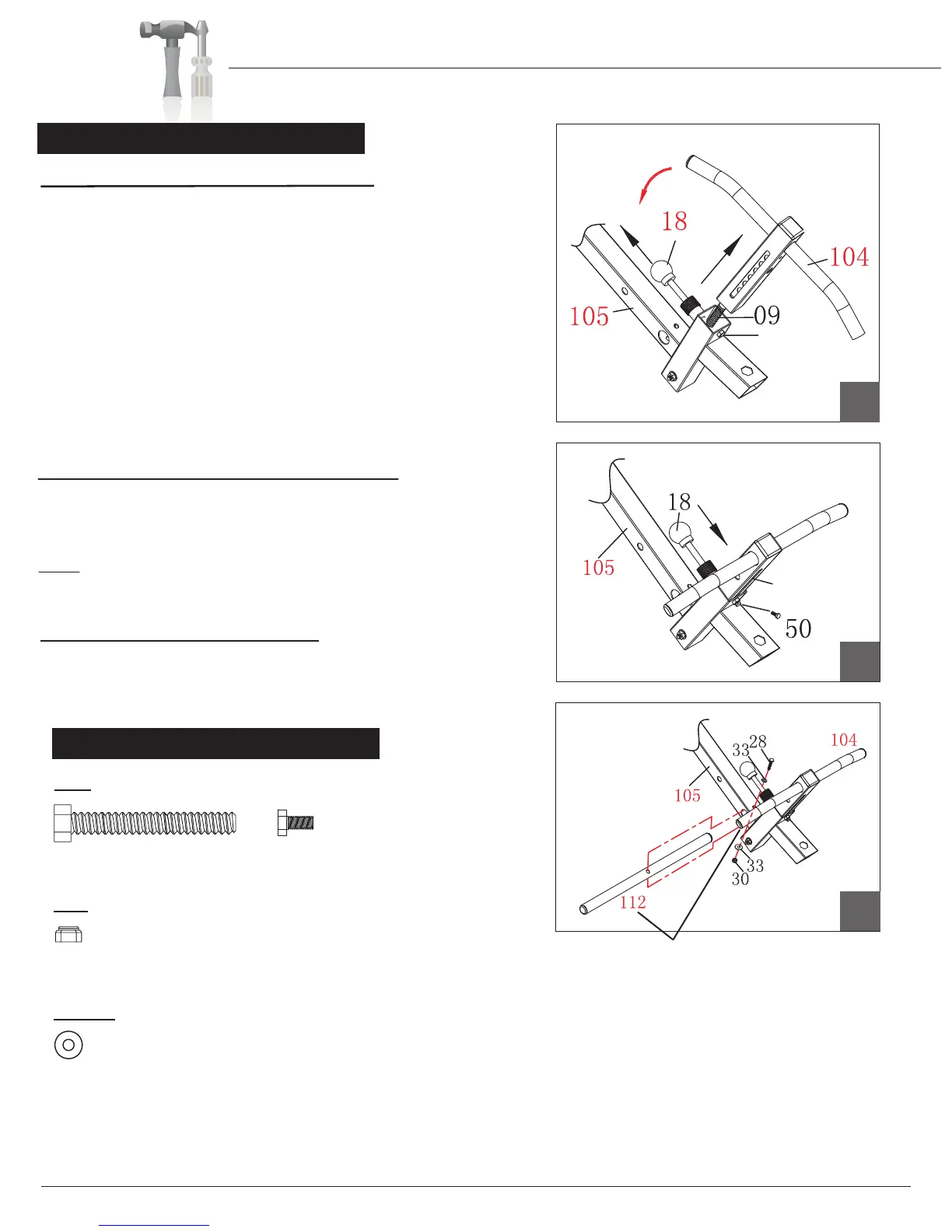
A s s e m b l y S t e p 3
Hardware Required
A.) Adjustable Ankle Brace Assembly
C.) Ankle Brace Tube Assembly
Slide the Ankle Brace Tube (#112) through the corresponding
Take the illustrated assembly which is composed of
parts (#105),(#104),(#18), and (#09)
out of the box. Pull up the
Ankle Brace Lock Pin (#18) as illustrated and, at the
same time, pull the Adjustable Ankle Brace (#104) out
of the Height Adjustment Tube (#105) SLOWLY. (You will notice
that there is a Spring (#09) that pulls downward
as you pull the
Adjustable Ankle Brace (#104) out).
After you free the
Adjustable Ankle Brace (#104) out as shown in drawing A,
rotate it 90 degrees counter-clockwise so that the circular round
holes face toward the Ankle Brace Lock
Pin (#18), and the long
oval slot faces downward toward the Hex Bolt (#50). Insert the
Adjustable Ankle Brace (#104) back into the Height Adjustment
Tube (#105) and release the Ankle Brace Lock Pin (#18).
NOTE: For your safety, always ensure that the Ankle Brace Lock
Pin (#18) is fully inserted into the circular round hole setting that
holds your feet snugly before inverting.
Next, insert Hex Bolt (#50) through the bottom hole shown in
drawing A and through the long oval slot and tighten.
Please ensure the assembly now looks like drawing B and that
the Ankle Brace Lock Pin (#18) is fully engaged down into a hole.
set of holes on the Height Adjustment Tube (#105). Then,
secure this assembly by using one Hex Bolt (#28), two Washers
(#33) and one Lock Nut (#30) as sequenced in diagram C.
Long oval slot
facing downward
Rotate
90 degrees
B.) Adjustable Ankle Brace Assembly (II)
Hole for
Step B.
IT8020