D
56
C
B
A
Page 8
Hardware Required
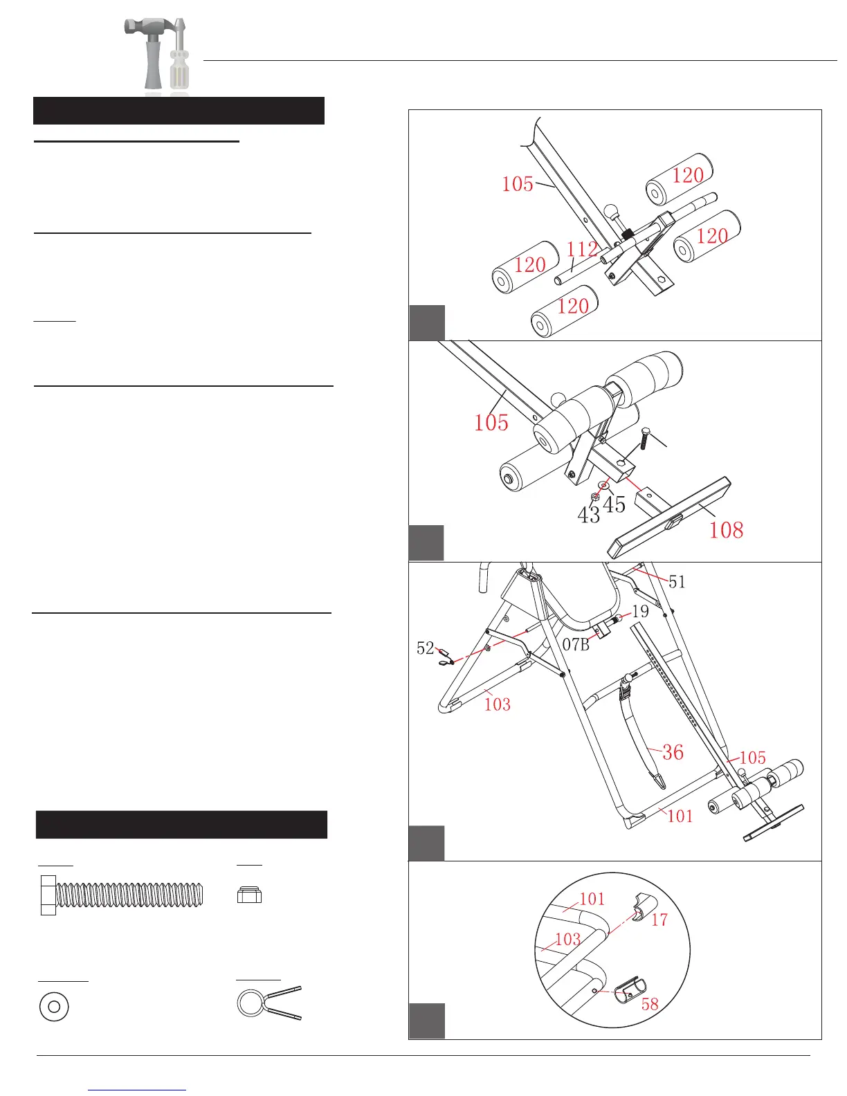
D.) Plastic Clip Base Protectors
The 4 Plastic Clips (#17/#58) add stability and safety to the unit.
The assembly process is now complete, HOWEVER , please do not
use the inversion table until you have completed reading the manual
to learn about the safety features and operation procedures.
the
Slide the Safety Bar (#51) into either the top set of holes or
the bottom set on the Rear Base (#103) and secure it with a
Quick Clip (#52).
Height Adjustment Tube (#105) up or down.
Ensure that four Plastic Clips (#17/#58) are installed on the
Front Leg Tube (#101) and Rear Base (#103) before using
the unit. If for any reason they are not installed on the unit,
follow these simple steps to install them.
First, lift the front end up and you will notice that there is a hole
on the bottom. Insert the clip pin on the Plastic Clip (#17) into
the hole on the Front Leg Tube (#101) and snap it into place.
Repeat this process to snap the Plastic Clip (#58) into the
Rear Base (#103) if neccessary.
#43 Lock Nut (M8)
[1 piece]
Bolts
#56 Hex Bolt (M8x45 mm)
[ 1 piece]
#45 Washer (M8)
[1 piece]
#52. Quick Clip
[1 Piece]
Washer
Nut
Others
A s s e m b l y S t e p 4
A.) Foam Roller Assembly
Slide the two Foam Rollers (#120) onto the Height
Adjustment Tube (#105) and another two on the Ankle
Brace Tube (#112). Apply soapy water to the tubes if the
foam rollers do not slide on easily.
B.) Adjustable Foot Tube Assembly
Slide the Adjustable Foot Tube (#108) with the “UP” sticker
facing up in the Height Adjustment Tube (#105) and secure
it with one Hex Bolt (#56), one Washer (#45) and one Lock
Nut (#43).
NOTE: Any settings should always hold your feet snugly
during inversion for your safety.
(ALWAYS WEAR ATHLETIC SHOES BEFORE INVERTING!)
C.) Height Adjustment Tube Assembly
With the help of an assistant, attach the Height Adjustment
Tube (#105) to the Backrest
F
rame (#07B)
by pulling the
Height Selector Lock Pin (#19)
out and simultaneously
sliding the Height Adjustment Tube (#105) in. Release the
Height Selector Lock Pin (#19) to any setting for now.
The Height Adjustment Tube (#105) is designed to
accommodate the height of various users; set it accordingly
by pulling the
Height Selector Lock Pin (#19)
as you slide
Assembly Instructions
IT8020