S T E P
Ь Я Be careful to assemble all components
in the sequence they are presented.
NOTE: Finger tighten all hardware in this step.
Do Not wrench tighten until the end of Step 3.
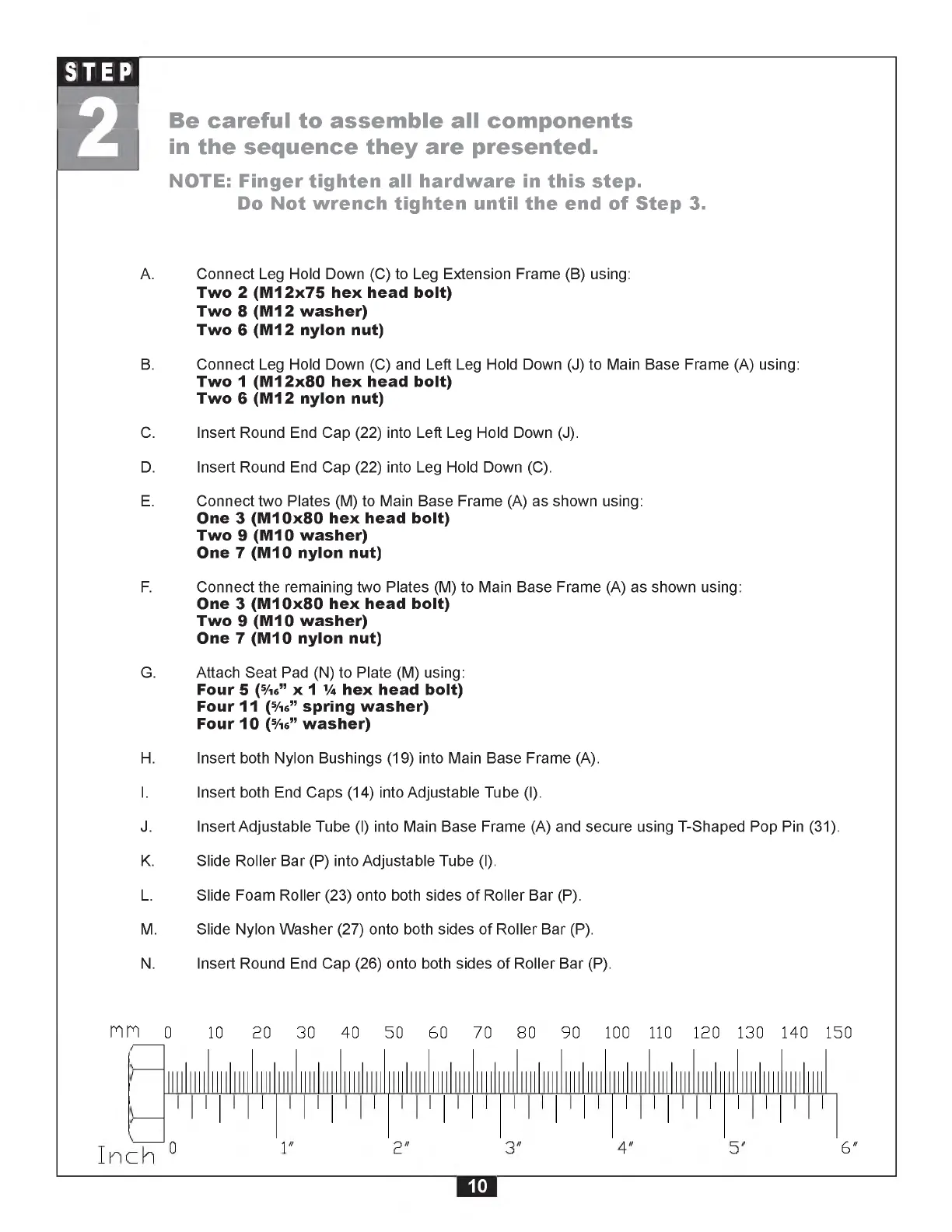
A. Connect Leg Hold Down (C) to Leg Extension Frame (B) using:
Two 2 (M 12x75 hex head bolt)
Two 8 (M12 washer)
Two 6 (M12 nylon nut)
B. Connect Leg Hold Down (C) and Left Leg Hold Down (J) to Main Base Frame (A) using:
Two 1 (M 12x80 hex head bolt)
Two 6 (M12 nylon nut)
C. Insert Round End Cap (22) into Left Leg Hold Down (J).
D. Insert Round End Cap (22) into Leg Hold Down (C).
E. Connect two Plates (M) to Main Base Frame (A) as shown using:
One 3 (M 10x80 hex head bolt)
Two 9 (M10 washer)
One 7 (M10 nylon nut)
F. Connect the remaining two Plates (M) to Main Base Frame (A) as shown using:
One 3 (M 10x80 hex head bolt)
Two 9 (M10 washer)
One 7 (M10 nylon nut)
G. Attach Seat Pad (N) to Plate (M) using:
Four 5 (5/i6” x 1 1/4 hex head bolt)
Four 11 (5/16” spring w asher)
Four 10 (5/16” washer)
H. Insert both Nylon Bushings (19) into Main Base Frame (A).
I. Insert both End Caps (14) into Adjustable Tube (I).
J. Insert Adjustable Tube (I) into Main Base Frame (A) and secure using T-Shaped Pop Pin (31).
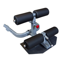
K. Slide Roller Bar (P) into Adjustable Tube (I).
L. Slide Foam Roller (23) onto both sides of Roller Bar (P).
M. Slide Nylon Washer (27) onto both sides of Roller Bar (P).
N. Insert Round End Cap (26) onto both sides of Roller Bar (P).
m
0
10 20 30 40 50 60 70 80 90 100 110 120 130 140 150
6 "
10