Do you have a question about the Body Solid GCLP100 and is the answer not in the manual?
Rules to minimize risk when using the equipment, including inspection and safe operation practices.
Essential safety measures to follow while operating the GCLP100 exercise machine.
Guidelines for safe assembly, including reading instructions and proper setup.
Information on how to get service, order replacement parts, and contact customer support.
List of basic tools needed before starting the assembly of the GCLP100.
Key requirements for setting up the GCLP100, including surface, space, and bolt tightening.
Helpful advice for a smooth assembly process, including reading notes and handling parts.
Detailed list of all parts and their corresponding part numbers for the GCLP100.
List of all hardware components, including bolts, washers, and nuts, with quantities.
Illustrations and quantities for M12 and M10 bolts, and M10 screws.
Illustrations and quantities for M8 screws, M8/M10 washers, and M10 large washers.
Illustrations and quantities for M10/M8 washers and M10/M8 lock washers.
Illustrations and quantities for M12/M10 nylon lock nuts and M8 large washers.
Instructions for attaching the Front Upright (A) and Rear Upright (C) to the Base Frames (B).
Connects the Foot Plate Support Frame (D) and Center Frame (F) to the Base Frames (B).
Securing the Foot Plate (E) to the Foot Plate Support Frame (D) and Front Upright (A).
Attaches the Seat Pad (26) to Carriage (J) and inserts Guide Rods (G).
Installs Carriage (J) onto Guide Rods (G) and inserts Rubber Bumpers (16).
Connects the Weight Horn (H) to the Carriage (J) and adds Weight Plate Bumpers (17).
Attaches the Back Rest Frame (N) to the Carriage (J) using specified hardware.
Connects the Back Rest Adjustment Tube (Q) to the Carriage (J) with bushings and a shaft.
Inserts the Back Rest Telescoping Tube (P) into the Adjustment Tube (Q) and screws in the Pop Pin (29).
Secures the Back Pad (27) to the Back Rest Frame (N) with screws and washers.
Connects the U Bracket (S) and Handle Bar (R) to the Carriage (J) with hardware and a torsion spring.
Attaches the Shaft (32) to the U Bracket (S) using screws, washers, and lock washers.
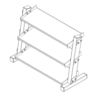
A detailed visual representation of all GCLP100 parts and their assembly relationships.
| Product Name | Body Solid GCLP100 |
|---|---|
| Category | Fitness Equipment |
| Material | Steel |
| Color | Black |
| Weight Capacity | 1000 lbs |
| Adjustability | Adjustable |
| Warranty | Lifetime |