10
STEP
2
Be careful to assemble all components
in the sequence they are presented.
NOTE:
Wrench tighten ALL hardware at the end of STEP 2C. Some components may be
pre-assembled. Nylon lock nuts will not fully screw onto bolts, they must be wrench
tighten to fully go on.
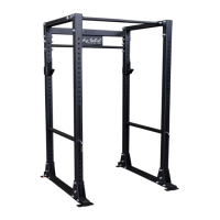
2A. AttachTopSideFrames(C)toFrontUprights(B)using:
4 - (#1) M16x110mm Hex Head Bolt
8 - (#3) M16 Regular O.D. Washer
4 - (#5) M16 Nylon Lock Nut
2B. AttachTopSideFrames(C),TopRearFrame(E)andRearUprights(B)
togetherusing:
8 - (#1) M16x110mm Hex Head Bolt
12 - (#3) M16 Regular O.D. Washer
4 - (#4) M16 Large O.D. Washer
8 - (#5) M16 Nylon Lock Nut
2C. AttachChinUpBar(D)toTopSideFrames(C)using:
4 - (#1) M16x110mm Hex Head Bolt
4 - (#3) M16 Regular O.D. Washer
4 - (#4) M16 Large O.D. Washer
4 - (#5) M16 Nylon Lock Nut
NOTE:
It is recommedated to install the equipment with at least two persons.