5
Installation
Power and Grounding
The AC line cord has a three-prong plug which must be plugged into a three-wire grounded 120-volt, 60 Hz outlet.
Note: It is important to ground the amplifier properly.
Input Connections
Microphone Connections
Two low-impedance balanced microphones may be connected simultaneously to the corresponding screw termi-
nals on the rear panel of the amplifier.
Microphone Precedence
A built-in circuit provides microphones’ precedence over the AUX channel. For this function, a customer-supplied
normally-open SPST switch must be connected to the MUTE terminals. When the contacts are closed, the micro-
phone will have precedence.
AUX
The AUX inputs may be used for any signal source having a line-level (greater than 85mV) output.
TEL
A balanced isolating transformer input for a telephone line is provided. A 600-ohm telephone line may be connected
to the TEL terminals.
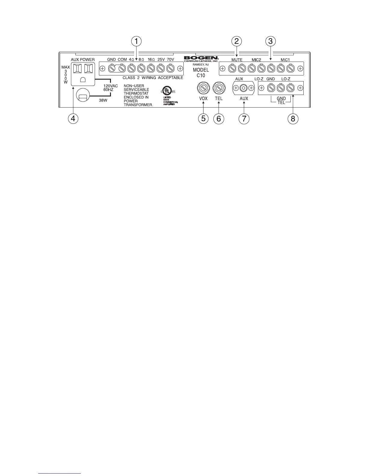
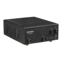
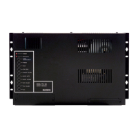
Rear Panel
1. Amplifier Output
Screw terminal strip containing all available speaker outputs.
2. Mute Input
Screw terminal input for microphone precedence.
3. MIC1/MIC2
Screw terminal input for Lo-Z balanced microphone signal.
4. AUX Power
A grounded, unswitched AC convenience receptacle with 300W maximum capacity is provided for external equipment.
5. VOX SENS Control
Variable control for adjusting the TEL input signal level trigger point for automatic muting of the AUX input.
6. TEL Volume Control
Adjusts the telephone paging level.
7. AUX Input
RCA unbalanced, high-impedance input (AUX is switch-selectable with MIC2).
8. TEL Input
Screw terminal input for 600-ohm balanced telephone signal.