Do you have a question about the Bogen TPU250 and is the answer not in the manual?
Essential safety guidelines for installation and use, covering reading instructions, ventilation, liquid spills, and wiring.
Guidance on installing the amplifier, including weight and heat considerations.
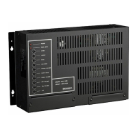
Instructions for securely mounting the amplifier to a wall using provided screws.
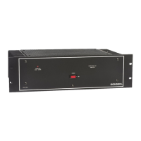
Details on mounting the amplifier in a standard 19-inch rack, including flange orientation.
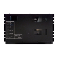
Instructions on making input connections to the amplifier's terminal strip and RCA connectors.
Details on connecting the 600-ohm dry loop telephone page signal to the T and R terminals.
How to connect a background music source via RCA or screw terminals, and using a matching transformer.
Connecting a low impedance microphone, including wire connections and cable types.
Connecting a telephone ring signal or contact closure to activate the night ringer.
How to connect two TPU250 amplifiers in tandem to increase total output power.
Procedure for replacing the input cover after making connections.
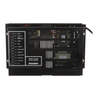
Connecting 70-volt or 25V speakers using shielded, twisted pair cable.
Using an external amplifier with the TPU250, including a resistor voltage divider.
Connecting a WMT1A transformer for a 600-ohm balanced output, useful for long lines.
Procedure for replacing the output cover after making connections.
Explanation of the POWER IND and PEAK LEVEL LEDs and their functions.
The POWER IND LED indicates when AC power is applied to the amplifier.
The PEAK LEVEL LED indicates when the speaker output signal approaches maximum level.
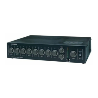
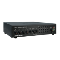
Detailed explanation of various controls on the amplifier.
Adjusts the level of the telephone page output.
Adjusts the level of the background music output.
Controls the level of background music heard during a paging announcement.
Adjusts the level of the microphone page output.
Adjusts the level of the night ringer tone output.
Adjusts the amount of Aphex Aural Exciter effect mixed into the page signal.
Adjusts high and low frequency response of the paging system.
Sets sensitivity for voice detection to mute background music.
Controls the level at which the amplifier limits the output signal.
Step-by-step guide for manual adjustment of output levels using TEL VOLUME and ALC.
| Channels | 1 |
|---|---|
| Power Output | 250 Watts |
| Input Impedance | 10k ohms |
| Output Impedance | 70V, 25V, 4Ω |
| Outputs | Screw terminals |
| Power Requirements | 120V AC, 60 Hz |
| Input Sensitivity | 1V for full output |
| Total Harmonic Distortion (THD) | <0.5% at rated power |