OUTLET BOXES. Where flush-mounting switches
are used, single-gang outlet boxes will be installed. In
installing such boxes, make certain to place them in a
location that permits personnel to operate the switch
while communicating via the room speaker. The normal
height (above the finished floor) for room switches is
approximately four feet, while speakers are normally
placed at a height of about seven and one-half feet.
SOLDERING INSTRUCTIONS
SOLDER.
Do not use acid-core solder or acid paste.
Make all solder connections with standard
60/40
resin-
core radio solder. Do not apply excessive heat. Solder-
ing irons or guns from 75 to 200 watts will provide
ample capacity.
GROUNDS.
Do not connect cable shields to earth
ground or to convenient metal objects.
It
is important to
connect cable shields only as shown in the wiring
diagrams.
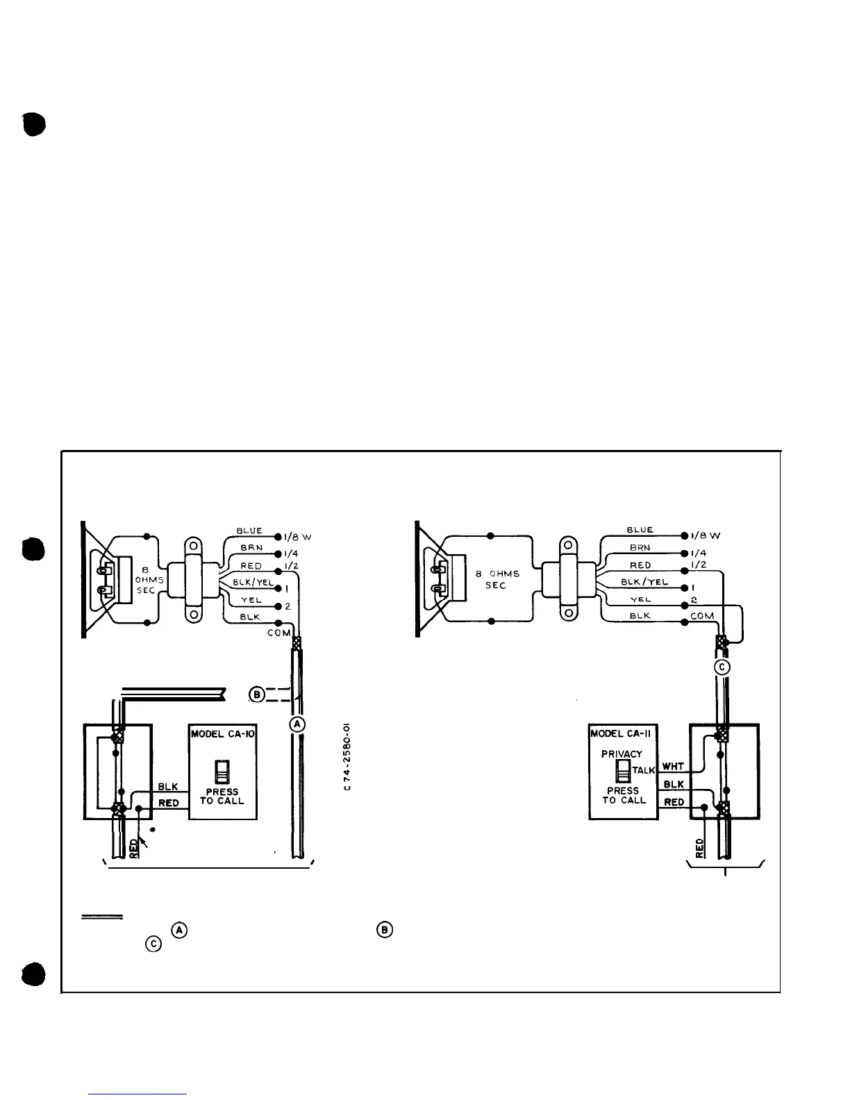
CLASSROOM WIRING
CONNECTIONS
Refer to the left-hand column of Table I for the type
of classroom operation used in your system. The corres-
ponding right-hand column calls out the wiring diagram
required. Solder the wires as shown in the proper dia-
gram and wrap with insulating tape.
CAUTION
Make certain to connect
all
wires in accor-
dance with the color codes given on the dia-
gram.
SECURING SWITCHES
The Model CA switches are designed for flush
mounting in a standard single-gang electrical outlet box,
BOGEN
25-VOLT
ROOM
LINE MATCHING
SPEAKER TRANSFORMER
(SEE NOTE-P)
(SEE NOTE-I)
--
I
--
22AWG MIN.(TYP.)
(BELDEN 8937, OR
EOUIV.)
TO CONSOLE ‘SWITCH BANK
BOGEN
25-VOLT
ROOM
LINE MATCHING
SPEAKER TRANSFORMER
(SEE
NOTE-2)
TO CONSOLE
SWITCH BANK
NOTES :
I- CONNECT AS FOR NON-PRIVATE OPERATION, AS FOR NON-PRIVATE WITH ANNUNCIATOR,
OR AS
FOR PRIVATE WITH ANNUNCIATOR.
2-
MODEL
TS-2A
(1/2
WATT TAP) SHOWN.
SEE TEXT FOR
TS-I6A
TRANSFORMER
AND ADDITIONAL INFORMATION.
Figure
1
-
Connection Diagram,
Speaker
Installation
-3-