switch. Speak clearly into the control panel speaker
from a distance of approximately 12” (Note: Intercom
function switch must be depressed to receive VOICE
CALL IN from stations).
TO OPERATE EMERGENCY
Depress
EMERG
switch and speak clearly into panel
speaker. Message is transmitted to all stations regardless
of switchbank settings, program and intercom function
settings, and position of POWER ON-OFF switch.
ACCESSORY EQUIPMENT
LIGHT-ANNUNCIATOR CALL SYSTEM
If a light-annunciator call-in function is installed, the
optional Model SBL Switchbank panels have an annun-
ciator lamp above each station selector switch. Each sta-
tion has a call switch to light the appropriate lamp.
When lamp lights, move the corresponding switch to
“C”
position. The intercom channel is now open for
normal intercom communication. The control panel
also has a built-in tone alert to provide audible annunci-
ation that supplements switchbank lamps.
PRIVACY FUNCTION
Prevents the console operator from monitoring the
speaker station if the station is provided with the op-
tional CA-l 1 CALL/PRIVACY Switch. A station in
the Privacy mode will still receive messages from the
consolette.
TIME TONE OPTION
The external single-circuit time clock closes contacts
that are normally open to activate the optional Time
Tone Module SST-l for timed, preset signals to station
speakers. Connects to terminal strip on the rear of the
control panel.
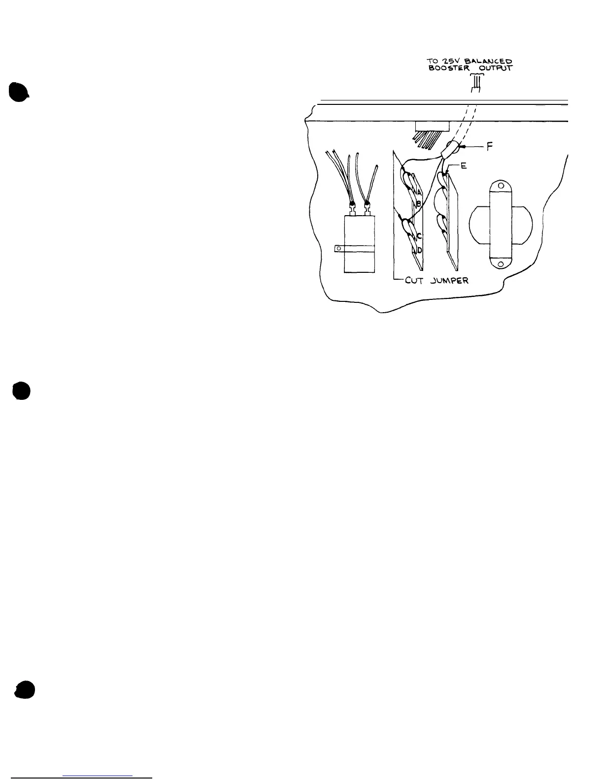
EXTERNAL BOOSTER AMPLIFIER
Model MT-60A or MT-
125B
(60 or 125 watts) provide
increased power output. To install, remove the MCT-1
top cover and cut the jumpers on the terminal strip
between points A, B and C, D as shown in figure 5.
Insert two-conductor shielded cable in hole F. Connect
25 V balanced output leads to terminal strip points B
and C. Connect the shield to E. Attach the cable from
the Tape Out/Booster output jack on the rear of the
MCT-1
to the Hi-Z input of the MT-60A or MT-125B.
Figure
5
-
Connecting Booster-Amplifier
MAINTENANCE
CAUTION
There are no user-replaceable parts within
the unit. Have all in
ternal
servicing done by
qualified service personnel.
BOGEN SERVICE
We are interested in your
Bogen
equipment for as
long as you have it. If trouble ever develops, do not
hesitate to ask our advice or assistance. Information can
be obtained by writing to Service Department,
Bogen
Division, P.O. Box 500, Paramus, N.J. 07652.
When communicating with us, give the model and
series designation of your unit. Describe the difficulty
and include details on the electrical connections to asso-
ciated equipment, and list such equipment. When we re-
ceive this information, we will send you service infor-
mation if the trouble appears to be simple. If the trouble
requires servicing, we shall send you the name and ad-
dress of the nearest
Bogen
authorized service agency to
which you can send your unit for repairs.
When shipping your unit, pack the amplifier well,
using the original shipping carton or a similar container
and filler material to prevent damage in transit. Send
the unit, fully insured and prepaid, via any responsible
carrier. The unit will be promptly repaired and returned
to you express collect.
-7
 Loading...