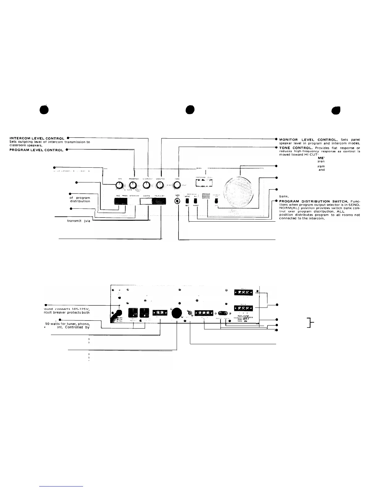
Fader control for
setting
level of radio or
phono/tape program,as indicated on output
meter. Mav be used with
MlC
level control for
program mixing.
MIC LEVEL CONTROL
Fader control for setting level of Mic 1 or Mic 2
program as
indicated
on output meter. May be
used with PROGRAM level control for mixing.
MICROPHONE FUNCTION SWITCH
When IN, connects microphone input, selected
by MIC level control, to program channel.
PROGRAM FUNCTION SWITCH
When IN,
permits transmission
material as determined by program
and program output switches.
INTERCOM FUNCTION SWITCH
PROGRAM OUTPUT M ER. Color coded to
clearly display 25V refe ce level.
__
gency
transmissions,
two-way intercom
SPEAKER. For program monitoring,
emer-
communication.
POWER SWITCH. Controls ac power to panel
and to equipment connected to rear panel con-
venience
outlets.
TONE ALERT (OPTIONAL). Provides audible
annunciation to supplement lamps on switch
When
IN, enables intercom Talk/Listen switch.
EMERGENCY SWITCH l
When IN. permits operator to
panel speaker) to all classrooms, regardless of
switch bank settings. Overrides all program and
intercom
functions. Operates
ev
en
when
POWER switch is OFF.
TALK/LIST(EN)
SWITCH .
When enabled by INTERCOM function switch.
permits operator to communicate with
room
selected
on switch bank without effecting pro-
gram distribution to remaining rooms.
De-
Pressed for TALK; released for
LIST(EN).
l PROGRAM OUTPUT SWITCH. SEND position
enables program distribution switch. SET posi-
tion disconnects program output from load for
monitoring or presetting prior to distribution.
Does not effect intercom functions.
l TAPE RECORDER INPUT. For playing output
from tape recorder on program channel. Ac-
Figure 6
-
Front view, MCT-1 Control Panel
cepts
standard 2-conductor phone plug which,
when inserted, automatically disconnects phono-
graph input.
AC POWER INPUT
3-wire cord with
gr
50/60
Hz source. Ci
panel andconvenience outlets.
CONVENIENCE OUTLETS
Each provides up to
or other auxiliary
equipme
front panel POWER switch.
TIME CLOCK INPUT .
For connecting external single-circuit time
clock. Clock closes normally open contacts to
activate optional Model SST-1A Module.
SWITCH BANK CONNECTION .
Cable terminated in
Il-pin plug connects three
shielded pairs plus annunciator wire from
switch bank. Also accommodates three lines for
optional telephone system.
MICROPHONE INPUTS. For low-impedance
balanced or unbalanced
mics.
Use 2-conductor
microphone cable
(Bogen
1006. or equiv.). Con-
nect
shield to terminal 1.
PHONO INPUT
Single-conductor
TUNER INPUT
shielded cable.*
INTERCOM CALL-IN LINE. Parallel
lines
from
classroom call-in switches. 2-conductor shielded
cable
(Bogen
BB
6450, or equiv.). Connect
shield to terminal 3.
l
TAPE RECORDER/BOOSTER INPUT. For recording
program material on external tape recorder and connecting
external booster
amplifier
2-conductor
shielded cable
(Bogen
BB
8450, or equiv.).’
*Accepts Cinch 13A. or equivalent.
Figure 7
-
Rear view, MCT-1 Control Panel
 Loading...