24 / 64
IOM Manual VF-W_ATEX_gb - Translation of original instructions in Italian - Rev 03_0 - 30/09/16
3. Retain shaft axially inserting the washers (4) rst and then snap rings (5) into their groves.
4. Fit connecting ange (6) onto the gearbox and lock it with the two bolts (7).
5. Mount limit-switch (10) onto connecting ange (6) and secure it with the two socket head bolts (8). Whilst
performing this, make sure that the dowel pin (1) is located in the grove machined into the bush trailing
the entire limit-switch device.
6. Finally insert the dust proof contact seal (9) carefully into its site. See gure for reference.
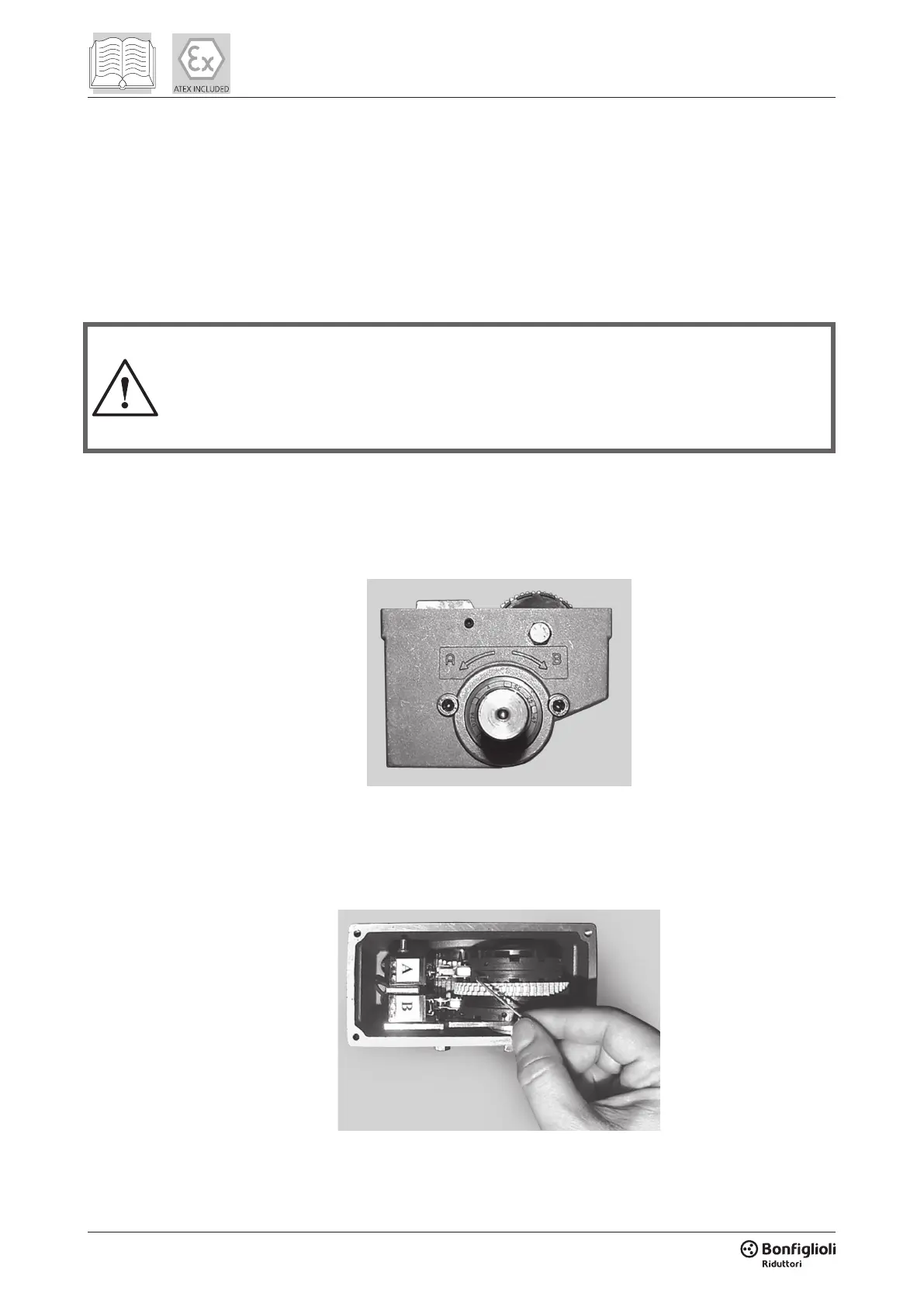
5.5.1 Setting of the limit-switch device (RVS)
Disconnect power to the electric motor before working on the limit switch device.
The device must only be installed and calibrated by specialist personnel, according to these
instructions and any other instructions provided with it or separately from it. All standards
applicable in the country or region of installation must also be respected.
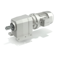
The micro switches carry the letters (A) or (B) which refer to the direction of rotation of the drive shaft.
To set the “open” and “close” positions of the equipment, rst install the gearmotor onto the framework.
Allow the drive pinion to mesh with the relative rack.
Thereafter, remove the lid from the top and follow the procedure, as described below:
1. Drive the gearmotor until either one of the two end positions is reached. Disconnect power. While
performing this, observe which direction the shaft is rotating, whether (A) or (B). Refer to raised arrows
on side of the housing.
 Loading...