Do you have a question about the Boraam PORTO SWIVEL Stool and is the answer not in the manual?
Lists all individual components included in the stool kit for assembly.
Details the fasteners and tools provided for assembling the stool.
Instructions for connecting the chair legs to the footrest, with initial loose tightening.
Guides the attachment of chair legs to the apron with swivel plate, then tightening.
Instructions for connecting the backrest to the seat cushion using provided hardware.
Details connecting the assembled base to the top section and final tightening.
Indicates the completion of the assembly and provides a critical safety warning.
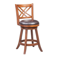
The Boraam Industries Porto Swivel Stool is a versatile and comfortable seating solution designed for various home environments, offering both functionality and style. This stool is engineered for ease of assembly and long-term use, making it a practical addition to kitchens, bars, or any area requiring elevated seating.
The Porto Swivel Stool serves as an elevated seating option, providing a comfortable perch for dining, socializing, or working at higher surfaces. Its primary function is to offer stable and supportive seating with the added convenience of a swivel mechanism, allowing users to rotate freely without moving the entire stool. This swivel feature enhances interaction in social settings and provides flexibility for tasks that require movement or access to different areas. The stool is designed to be sturdy and durable, capable of supporting regular use in a household setting. Its construction emphasizes both comfort and stability, ensuring a pleasant seating experience for extended periods. The inclusion of a footrest further enhances comfort by providing a place to rest the feet, reducing strain during prolonged sitting.
The Porto Swivel Stool is designed with several features that enhance its usability and user experience.
Maintaining the Porto Swivel Stool is designed to be simple, ensuring its longevity and continued aesthetic appeal.
| Product Name | PORTO SWIVEL Stool |
|---|---|
| Brand | Boraam |
| Category | Indoor Furnishing |
| Type | Stool |
| Style | Contemporary |
| Swivel | Yes |
| Seat Material | Faux Leather |
| Base Type | 4 Legs |
| Finish | Chrome |
| Weight Capacity | 250 lbs |
| Assembly Required | Yes |
| Material | Faux Leather |