-11-
"!&""(
8-.5<%"875B
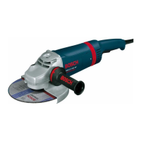
Disconnect tool from power source. Be sure
that wheel guard is in place for grinding. Place
BACKING FLANGE and GRINDING WHEEL
on the spindle. Thread on the lock nut and
tighten nut using the supplied lock nut wrench,
while holding the spindle lock in (Fig. 3).
TO REMOVE: Reverse procedure.
When using spin-on wheels, thread directly
onto the spindle.
LOCK NUT
TYPE 27
GRINDING
WHEEL
BACKING
FLANGE
SPINDLE
TYPE 27
GRINDING
WHEEL
LOCK NUT
SPINDLE
TYPE 27
WHEEL GUARD
BACKING
FLANGE
FIG. 3
TYPE 27 SPIN-ON
GRINDING WHEEL
"!&""(
8-.5875B
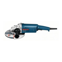
Disconnect tool from power source. Be sure
that wheel guard is in place for grinding.
When using mounting wheels, thread LARGE
BACKING FLANGE onto spindle, then place
GRINDING WHEEL on the spindle. Thread
on the lock nut and tighten nut using a lock
nut wrench provided with adapter kit, while
holding the spindle lock in (Fig. 4).
TO REMOVE: Reverse procedure.
When using spin-on wheels, thread directly
onto the spindle.
LOCK NUT
SPINDLE
TYPE 27
WHEEL
GUARD
FIG. 4
LARGE
BACKING
FLANGE
TYPE 27 SPIN-
ON GRINDING
WHEEL
TYPE 27
GRINDING
WHEEL
BM 1609929Y06 10-10:BM 1609929Y06 10-10 1/18/11 9:31 AM Page 11
 Loading...