Fan 1900, Fan 1900 DH 15
6 INSTALLATION
The bathroom extractor fan should only be installed, connected to electrical mains
and commissioned for use by qualied personnel in accordance with applicable laws!
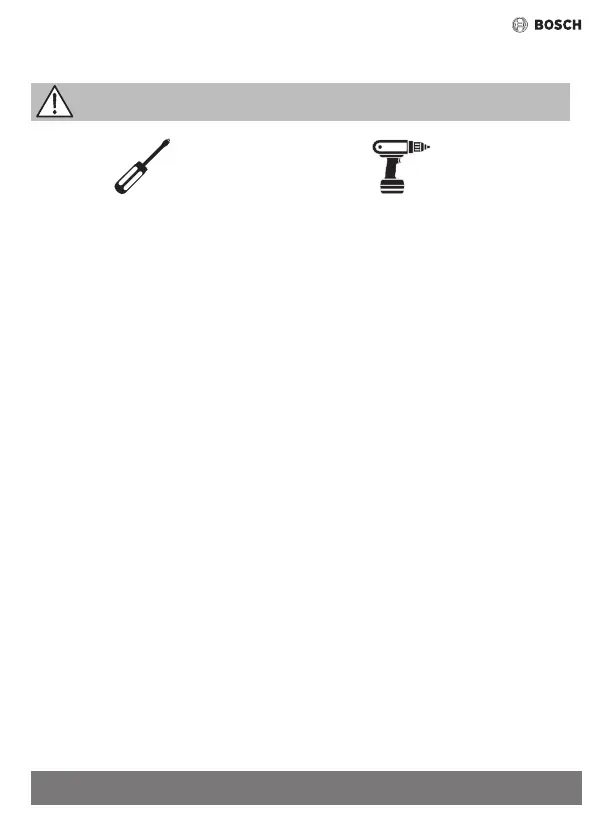
Necessary
tools:
Cross-tip screwdriver Drill-driver
Particular elements of the fan are shown on Fig. 1.
Installation procedure
• Precisely determine where the fan will be installed�
• Prepare the power cable indicated in chapter “Application and operating conditions”�
NOTE: Before starting make sure that the power cord is not live.
• Measure and drill holes for the fan and ø6 mm mounting pins included with the product�
NOTE: The arrangement of mounting holes and wires must be in accordance with Figure 7.
• Remove the front panel (1) and the rotor cover (2)� To remove the panel, unlock the locking mecha
-
nism (see Fig� 2�1) and then turn the panel counterclockwise (see Fig� 2�2)�
• Remove the electric cover (4) xed with screws (3)�
Applicable to the DH version: A sensor (11) is attached to the electric cover (4). Remove the cover
carefully so as not to damage the wiring harness connecting the sensor to the controller.
• Route the power cord in double insulation through the rubber grommet (7)� Insert a sucient length
of the cord so that the wires can be connected to the power terminals (5)� The minimum length of the
cable in the external insulation is 10 mm (inside the chamber)�
Before mounting the fan: remove all foreign objects from its inside; check manually that the fan
rotor moves freely; check that there is room for opening the non-return valve bae located at the
outlet of the bathroom extractor fan;
• Place the fan housing (6) and the mounting pins in the previously drilled holes�
ATTENTION: The fan must be mounted so that the electrical compartment is at the top.
• Mount the fan to the substructure by driving the screws into mounting pins through the mounting
holes (10)�
• Remove the outer insulation from the power cord and remove the 4 mm of insulation from the wires�
• Arrange the power cord and connect according to the electrical wiring diagram applicable to the
model installed�
NOTE: If there are unused wires in the cable then they should be insulated.
Applicable to the DH version: Insert the cores of the power cord into the corresponding holes of the
terminal strip� For ease of use, press the button on the clamps�
• Secure the cable against slipping out using the clamp (8) and screws (9)�
• Check if the seating of the cable conductors in the terminals (5) is solid�
• Check if the fan is rmly installed and correctly wired�
• Set the stop delay time and the humidity sensor sensitivity level using the potentiometer knobs (12)
on the controller�
• Check the tightness of the power cord�
-The power cord must be secured so that in case of ooding there is no ingress of water to live parts�