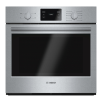
EasyManua.ls Logo

Bosch Benchmark Series User Manual

Bosch Benchmark Series
45 pages
To Next Page IconTo Next Page
Page #1 background imageLoading...
Page #1 background image
SERVICE MANUAL
for
Benchmark Series
Built-in Wall Ovens
HBLP451LUC / HBLP451RUC
HBLP451UC
HBLP651LUC / HBLP651RUC
HBLP651UC
HBLP751UC
HBLP751UCC
HSLP751UCC
This manual contains information that is necessary for
servicing the following Bosch electric built-in wall ovens:
HBLP451LUC, HBLP51RUC, HBLP451UC,
HBLP651LUC, HBLP651RUC, HBLP651UC,
HBLP751UC, HBLP751UCC, HSLP751UCC
This manual is designed to be used by qualified service
personnel only. Due to the complexity and the risk of
high-voltage electrical shock, Bosch does not recommend
that customers service their own units.
This material is intended for the sole use of BSH
authorized persons and may contain confidential and
proprietary information. Any unauthorized review, use,
copying, disclosure, or distribution in any format is
prohibited.

Table of Contents

Other manuals for Bosch Benchmark Series

Questions and Answers:

Bosch Benchmark Series Specifications

General IconGeneral
BrandBosch
ModelBenchmark Series
CategoryDishwasher
LanguageEnglish

Summary

Symbols Used in this Manual

Important Safety Information

Safety Before Servicing the Appliance

Safety precautions and warnings to follow before performing any service on the appliance.

General

Recap of Functional/Technical Changes

Overview of key functional and technical updates for Benchmark Series ovens.

Models

Details on the model number nomenclature and structure for wall ovens.

Model Descriptions

Specific descriptions for each Bosch Benchmark Series wall oven model.

Combination Ovens (Sets)

Information on how combination ovens are shipped and assembled by the customer.

Data Plate

Location and importance of the unit's model and FD number data plate.

Warranty

Details about the product warranty period and authorized service.

Operation

Allowable Operating Range by Cooking Mode

Minimum and maximum temperature ranges for each cooking mode.

Heating Elements

Description of the heating elements used in the ovens and their wattage.

Elements Used by Cooking Mode

Table detailing which heating elements are used for each cooking mode.

Element Duty Cycles

Duty cycle times for heating elements during Preheat and Regulate.

Setting Temperature Offsets

How to adjust oven temperature settings for consistent cooking.

Self-clean

Information on the self-clean function, especially for double ovens.

Cooling Fan

Details on the cooling fan's operation and role in maintaining temperatures.

Component Accessibility

Serviceable from the Front

List of components accessible for service from the front of the oven.

Serviceable from the Side

List of components accessible for service from the side of the oven.

Serviceable from the Rear

List of components accessible for service from the rear of the oven.

Serviceable from the Top

Description of access to components from the top front housing cover.

Top Access: Non-combination Models

Steps to access the service panel for non-combination models.

Top Access: Combination Models

Steps to access the service panel for combination oven models.

Service and Repair

Bottom-Hinge Doors

Serviceable parts and information for ovens with bottom-hinge doors.

Removing and Reinstalling the Door

Procedure for removing and reinstalling bottom-hinge oven doors.

Replacing the Hinges

Instructions for replacing hinges on soft-close bottom-hinge doors.

Replacing the 2-Pane Glass Pack

Procedure for accessing and replacing the oven door's 2-pane glass pack.

Side-Hinge Doors

Serviceable parts for ovens with side-hinge doors.

Removing and Reinstalling the Door

Procedure for removing and reinstalling side-hinge oven doors.

Aligning the Door

How to adjust the door alignment for smooth operation and proper closing.

Replacing the Hinge Assembly

Instructions for replacing the complete hinge assembly.

Door Latch/Motor Assembly

Details on the motorized door latch mechanism and its switches.

Replacing the Latch/Motor Assembly

Procedure for replacing the motorized door latch mechanism.

Oven High Temperature Cutout (HTC)

Information about the resettable high temperature cutout switch.

Resetting and Replacing the HTC

Steps to reset or replace the high temperature cutout switch.

Control Panel

Details on the components of the oven's control panel assembly.

Replacing the Front Panel Assembly

Procedure for replacing the entire front panel assembly.

Replacing the Display Module

Instructions for replacing the oven's display module.

Cavity Lights

Information about the oven's cavity lighting system and bulb replacement.

Replacing the Bulb

Procedure for replacing the halogen bulb in the oven cavity light.

Replacing the Lamp Receptacle Assembly

Procedure for replacing the lamp receptacle assembly, including lens and bulb.

Convection Fan, Ring Element and Motor

Details on the convection fan, ring element, and motor components.

Replacing the Convection Fan Blade

Procedure for replacing the convection fan blade.

Replacing the Ring Element

Instructions for replacing the oven's convection ring element.

Replacing the Convection Fan Motor

Procedure for replacing the convection fan motor.

Broil Element

Details on the broil element, its function, and testing.

Replacing the Broil Element

Procedure for removing and replacing the broil element.

Bake Element

Details on the bake element, its location, and testing.

Replacing the Bake Element

Procedure for accessing and replacing the oven's bake element.

Temperature Sensor

Information on the temperature sensor and its resistance readings.

Control Module (Relay Board) and Daughter Board

Information about the control module and daughter board functions.

Replacing the Control Module or Daughter Board

Procedure for replacing the oven's control module or daughter board.

Cooling Fan

Description of the cooling fan assembly and its function.

Replacing the Cooling Fan

Procedure for removing and replacing the cooling fan.

Hinge Receivers

Details on hinge receivers and their replacement procedure.

Replacing the Hinge Receivers (bottom-hinge)

Procedure for replacing hinge receivers on bottom-hinge models.

Troubleshooting

Error Codes

Table of error codes, their causes, and suggested troubleshooting actions.

Service Mode

Accessing and navigating the oven's service mode.

Accessing Service Mode

Steps to enter the oven's service mode for diagnostics and settings.

Setting the Option Code

Procedure for setting or changing the oven's option code.

Fault Trees

Flowcharts to guide troubleshooting of oven operational faults.

Wiring Diagrams and Schematics

Wire Color Key

Key to wire colors used in the oven's wiring diagrams.

Strip Diagrams

Element strip diagrams for single/upper and lower oven cavities.

ADDITIONAL REFERENCES

QuickFinder

References to additional documents and resources available on QuickFinder.

Technical Support

Contact information and availability for authorized service technical support.

Related product manuals