42
|
Bosch 96% AFUE Gas Furnace Installation, Operation & Maintenance
04.2019 | Bosch Thermotechnology Corp.
Data subject to change
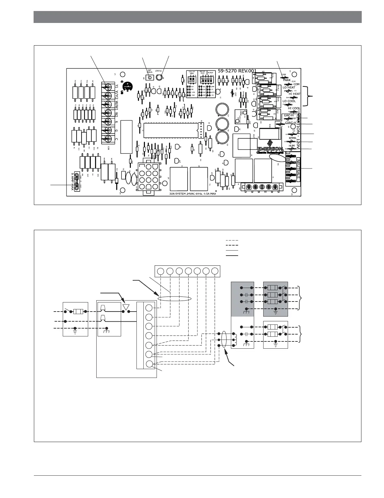
Figure 35
Fault LEDLast error buttonThermostat connections
Fuse
Unused blower terminal
Blower connections
EAC
Blower power input
Unit power input
(115V/60HZ)
Transformer
Humidifier
Neutral terminals
Furnace Control
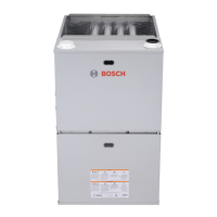
Figure 36
115V FIELD-
SUPPLIED
DISCONNECT
J-BOX
24V
TERMINAL
BLOCK
FOUR-WIRE
HEATING-ONLY
NOTE 1
NOTE 2
FIELD-SUPPLIED
DISCONNECT
CONDENSING
UNIT
THREE
WIRE
FURNACE
C
O
N
T
R
O
L
R
G
C
GND
GND
FIELD 24V WIRING
FIELD 115V, 208/230V, WIRING
FACTORY 24V WIRING
FACTORY 115V WIRING
208/230V
THREE
PHASE
208/230V
SINGLE
PHASE
BLOWER DOOR
SWITCH
WHT
BLK
WHT
BLK
NOTES:
Connect Y1, Y / Y 2 -terminal in furnace as shown for proper blower operation.
Some thermostats require a "C" terminal connection as shown.
If any of the original w ire, as supplied, must be replaced, use
same type or equivalent wire.
GND
(two stage cooling system thermostat)
TERMINALS
1.
2.
3.
R
G
Y/Y2
C
Y1
W1
W/W1
Y1
W2
W2
NOTE 3
Y1 connect two-stage cooling thermostat Y1(first stage cool) terminal.
4.
Y/Y2 connect two-stage cooling thermostat Y2(second stage cool)
terminal.
Y/Y2 connect single stage cooling system thermostat Y terminal.
NOTE 4
5.
NOTE 5
Please connect W/W1 with single stage heat system thermostat terminal
W,and W2 reserved.
6.
Y2
Heating and Cooling Application Wiring Diagram with 2-Stage Thermostat