22
|
Bosch Climate 5000 Series Ductless Air Conditioner / Heat Pump Outdoor Unit Service Manual
04.2020 | Bosch Thermotechnology Corp.Data subject to change
7 Wiring Diagrams
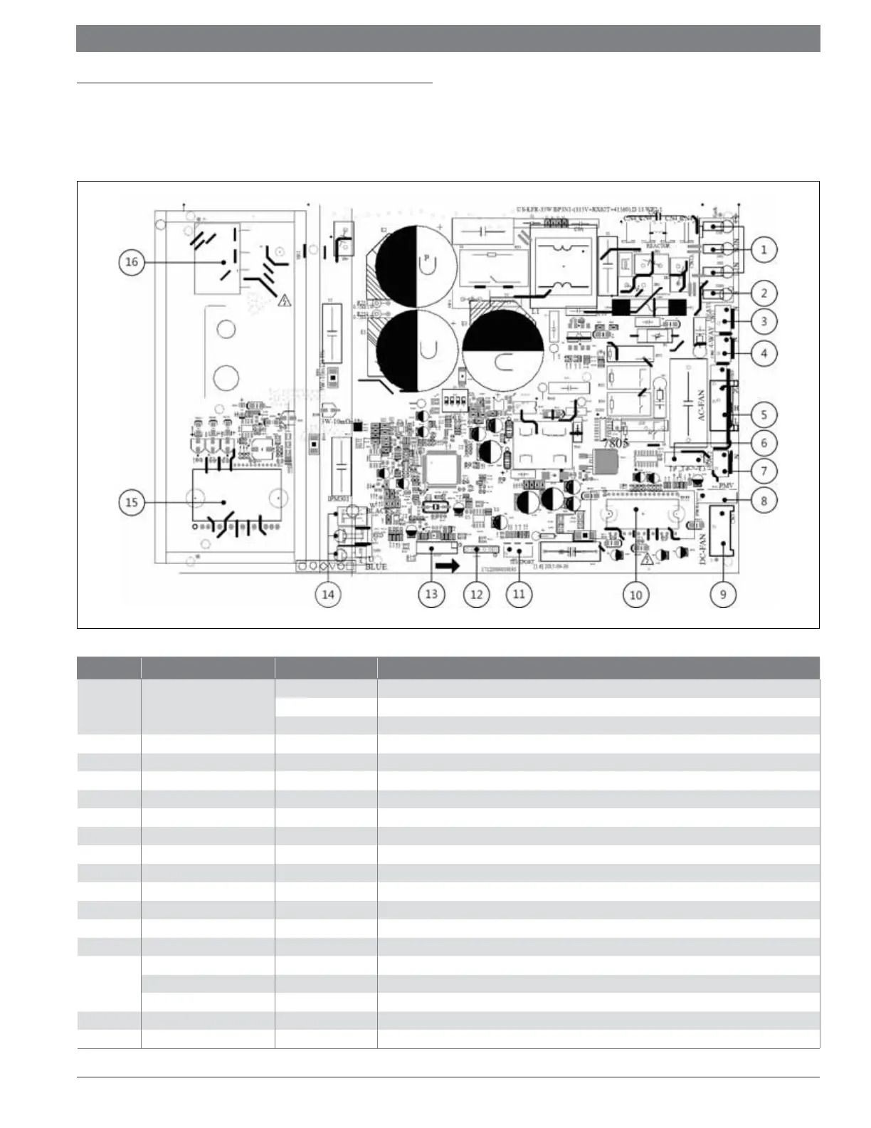
7.1 ODU PCB & IPM
7.1.1 PCB: Regular 115V Single Zone 12K
BMS500-AAS012-0CSXRB
Figure 12
Number Name CN# Description
1 Power Supply
CN3 Earth: connect to Ground
CN1 N_in: connect to N-line (100-130V AC input)
CN2 L_in: connect to L-line (100-130V AC input)
2S
CN16 S: connect to indoor unit communication
3HEAT1
CN17 connect to compressor heater, 100-130V AC when is ON
44-WAY
CN60 connect to 4 way valve, 100-130V AC when is ON.
5 AC-FAN
CN25 connect to AC fan
6 TP T4 T3
CN21 connect to pipe temp. sensor T3, ambient temp. sensor T4, exhaust temp. sensor TP
7HEAT2
CN15 connect to chassis heater, 100-130V AC when is ON
8 PMV
CN31 connect to Electric Expansion Valve
9 DC-FAN
CN7 connect to DC fan
10 FAN_IPM
IPM 501 IPM for DC fan
11 TESTPORT
CN6 used for testing
12 EE_PORT
CN505 EEPROM programmer port
13 MCUPORT
CN507 connect to PC communication
14
W
CN28 connect to compressor
V
CN29 0V AC (standby)
U
CN30 10-230V AC (running)
15 COMP_IPM
IPM 301 IPM for compressor
16 BR1
BR1 Bridge
Table 16
 Loading...