D263/D273 Series | Installation Instructions | 3.0 Wiring
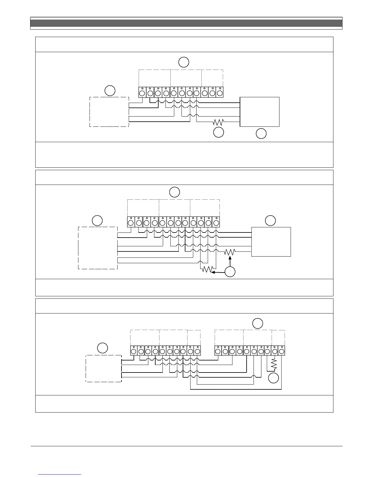
Figure 6: D273THS/D273THC/D273THCS Wiring
1
2
3
1 2 3 4 5 6 7 8
Input Voltage
10 to 30 VDC
+
IN
+
OUT
–
IN
–
OUT
Alarm Contacts
Normally Open
Smoke Detector
Power
Alarm
Loop
+
–
+
–
+
IN
+
OUT
–
IN
–
OUT
9
10
Auxiliary
Contact
N
O
C
11
N
C
Black
Yellow (+24 V) or
Red (+12 V)
Blue
Blue
4
1 - Last detector
2 - Control panel
3 - EOL resistor
4- D275 EOL Power Supervision Module
Note: Auxiliary contact wiring is for the D273THS,
D273THC, and D273THCS Models only
Figure 7: D273IS Wiring
Smoke Power
+
–
+
–
Heat Alarm Loop
Smoke Alarm Loop
+
–
2
1 2 3 4
Input Voltage
10 to 30 VDC
+
IN
+
OUT
–
IN
–
OUT
5 6 7 8
Isolated Heat
Output
+
IN
+
OUT
–
IN
–
OUT
9
10
Auxiliary Contact
Normally Open
11
Black
Yellow (+24 V) or
Red (+12 V)
Blue
Blue
12
+
IN
+
OUT
–
IN
–
OUT
1
3
4
1 - Last detector
2 - Control panel
3- EOL resistor
4 - D275 EOL Power Supervision Module
Figure 8: D273THR/D273THSR Wiring
Smoke Power
+
–
+
–
Alarm Loop
1 2 3 4 5 6 7 8
Input Voltage
10 to 30 VDC
+
IN
+
OUT
–
IN
–
OUT
Alarm Contacts
Normally Open
+
IN
+
OUT
–
IN
–
OUT
2
910
Trouble
Relay
T- T+
1 2 3 4 5 6 7 8
Input Voltage
10 to 30 VDC
+
IN
+
OUT
–
IN
–
OUT
Alarm Contacts
Normally Open
+
IN
+
OUT
–
IN
–
OUT
910
Trouble
Relay
T- T+
3
1
1 - Last detector
2 - Control panel
3- EOL resistor
Bosch Security Systems, Inc. | 02/06 | 31341J
Available from A1 Security Cameras
www.a1securitycameras.com email: sales@a1securitycameras.com
4