6 720 680 223
Installation instructions
15
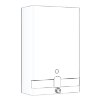
Fig. 17 Vertical venting installation (twin pipe penetra-
tion)
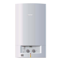
Fig. 18 Vertical venting installation - Masonry Chim-
ney (combustion air piping not shown)
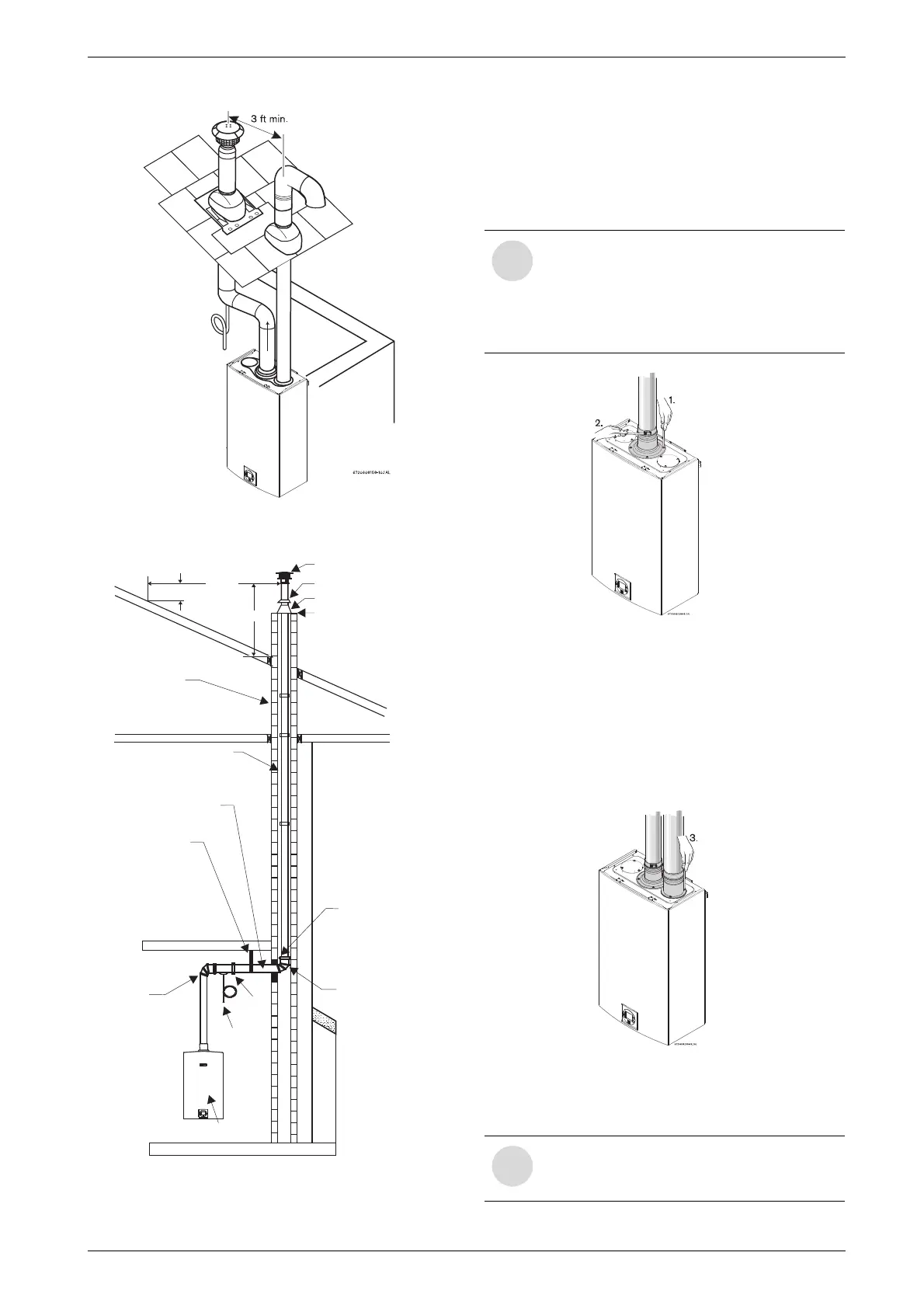
3.3.4 Vent connections
B Attach the flue gas exhaust accessory (8 705 504
151) to the top of the unit (position 1) using the 4
screws and gasket provided. Fully insert stainless
steel vent pipe 1.5” minimum into the accessory and
tighten the clamp (position 2).
Fig. 19
B Attach the combustion air inlet accessory (8 705
504 154) to the top of the unit (position 3) using the
3 screws and gasket provided, and install air intake
pipe over the accessory. NOTE: The appliance has
the option to mount the combustion air inlet acces-
sory on the top right or on the top left side of the
heater. The combustion air inlet that is not used must
be kept sealed.
Fig. 20
B Ensure that exhaust vent pipe is fully inserted in collar
to enable proper connection.
CHIMNEY
MORTAR
HANGERSTRAP
HORIZONTAL RUN
1/4"RISE/FT
ELBOW
APPLIANCE
MAY BEINSULATED
IFNECESSARY
6720608158-14.2AL
HOSE
CLAMP
ELBOW
RAINCAP
STORMCOLLAR
SILICONESEAL
FLASHING
CONDENSATE
DRAIN
2'MIN.
10'MIN.
3'MIN.
NOTE: Vent pipe must be completely
vertical when inserting or gasket inside
exhaust accessory can become
displaced. Exhaust accessory can be
removed with vent pipe attached to check
gasket position.
Exhaust venting must be 3" or 4" sealed
single wall stainless steel (AL29-4C) vent
pipe.