Do you have a question about the Bosch Evolution 500 Series and is the answer not in the manual?
Lists necessary tools and advises on avoiding static discharge damage to the PCB.
Steps to power off the appliance and remove the front cover for access.
Details on disconnecting various electrical strip connectors, ignition wires, and power cord.
Steps to physically detach the control unit from the water heater.
Locate rating plate to determine model number and gas type for jumper settings.
Install jumpers on the PCB according to model and gas type arrangements.
Reconnect all electrical connectors, wires, and power cord to the new control unit.
Replace rear cover, secure control unit, and power up the appliance.
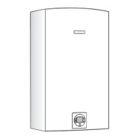
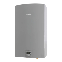
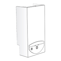
This document is a service bulletin (G3-24) from Bosch, detailing the procedure for replacing the control unit in several models of water heaters: 715ES, C800ES, 2400ES, 2700ES, Evolution 500, and Integra 500. It serves as a comprehensive guide for technicians, covering preparation, removal of the old unit, installation of the new unit, and post-installation checks.
The primary function of this service bulletin is to provide step-by-step instructions for replacing the control unit (Printed Circuit Board or PCB) in specific Bosch water heater models. The control unit is the "brain" of the water heater, responsible for managing its operations, including ignition, temperature regulation, safety features, and communication with other components. A faulty control unit can lead to various operational issues, making its replacement a critical maintenance task. The document ensures that the replacement process is performed correctly, maintaining the appliance's functionality and safety.
While the document focuses on replacement, the control unit itself enables several usage features of the water heater:
In summary, this service bulletin is a critical document for maintaining Bosch water heaters, ensuring that control unit replacements are performed accurately, safely, and efficiently, thereby extending the lifespan and reliable operation of the appliances.
| Brand | Bosch |
|---|---|
| Model | Evolution 500 Series |
| Category | Water Heater |
| Language | English |