2
|
G3-24 | 715ES, C800ES, 2400ES, 2700ES, Evolution 500, Integra 500
Service bulletin
Data subject to change without notice | Printed in the USA | BTC 710002318 D | 06.2012
Bosch Thermotechnology Corp.
Bosch Thermotechnology Corp.
50 Wentworth Avenue
Londonderry, NH 03053
Tel: 1-800-642-3111
Fax: 1-603-965-7581
www.bosch-climate.us
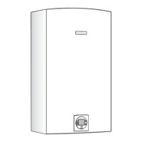
Locate rating plate sticker on right side of heater cover.
Determine model number (Fig.1, pos.A) and gas type (Fig.1,
pos.B).
Figure 1
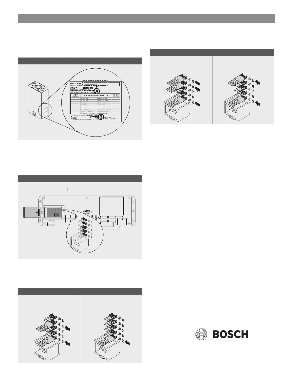
PCB jumper installation
In order for the appliance to work correctly, the proper jumpers
must be installed on the PCB board. (Fig.4)
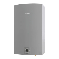
Backside of control unit
ackside o
control uni
Figure 4
Based on your model and gas type, jumpers should be installed
on the PCB in the following arrangement:
Model 2400 ES:
Natural
Gas
atura
Gas
Figure 5
Liquid
Propane
Models: C 1050 ES, 940 ES/ESO, 2700 ES, C 800 ES, 715 ES,
Evolution 500 (WTD 27), or Integra 500 (WTD 30)
Figure 7
Natural
Gas
Liquid
Propane
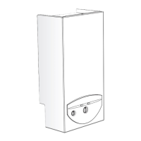
Replacing control unit
Once the appropriate jumpers have been determined, remove
rear cover of replacement control unit.
Install jumpers in the proper location on PCB.
Connect green ground wire from power cord to replacement
control board with Phillips head screw. (Fig. 3, pos. 8).
Reconnect black and white power cord wires to terminal
block on replacement control unit; Black -L (Load), White - N
(Neutral). Secure to terminal block by tightening flat head
screws. (Fig. 3, pos. 7).5. Reconnect yellow/green striped
ground wire to spade connection on replacement control
board. (Fig. 3, pos. 6).
Reattach large ignition wires to replacement control board (no
polarity). (Fig. 3, pos. 5).
Reconnect small electrical strip connector to replacement con-
trol board. (Fig. 3, pos. 4).
Reconnect medium sized electrical strip connector to replace-
ment control board. (Fig. 3, pos. 3).
Reconnect two large electrical strip connectors to replacement
control board. (Fig. 3, pos. 2).
Reseat rubber wire restraints in control unit. (Fig. 3, pos. 1).
Replace rear cover on unit using 6 Phillips screw (Fig. 2, pos.3).
Place control unit back into water heater and secure with 3
Phillips head screws. (Fig. 2, pos. 1).
Plug water heater power cord back into electrical outlet and
push On/Off button on water heater to “ON”.