Magnet Test:
Testing can be accomplished with the cover installed or removed. Place the magnet (Part #0700-01117 or
suitable bar magnet) on the detector as shown in Figure 4 / Figure 5 for approximately six (6) seconds to
activate the alarm LEDs and relays. This test will verify that the detector is within its intended limits.
Model FCD-350 Automatic Verfication:
The detector has a built-in sensitivity window verification feature. If the detector is within its calibrated
sensitivity range the detector LEDs will flash Green in standby or normal operation. If the detector drifts
outside its sensitivity range the LEDs will flash Red to indicate an out of sensitivity condition.
Smoke Test Port:
The FCD-350 has a smoke port for the introduction of smoke or simulated smoke without cover removal
by lifting the port tab. To test with aerosol smoke, use a
1
2
inch diameter pipe (or equivalent) at the
manufacturer's recommended minimum length to introduce the aerosol into the port. Press the pipe against
the detector housing and spray from the opposite pipe end, pipe elbows can be used. The amount of
aerosol is dependent on the duct air velocity, see below for estimated activations:
1,000-2,000 FPM: 3 seconds, 1 activation
2,000-3,000 FPM: 4 seconds, 1 activation
3,000-4,000 FPM: 4 seconds, 2 activations
The port must be closed after testing to avoid air leakage from the duct.
Test Switch:
Pressing the test switch will test the alarm relays, it will not test the detector's sensing element. The switch
must be pressed to reset the detector after an alarm activation.
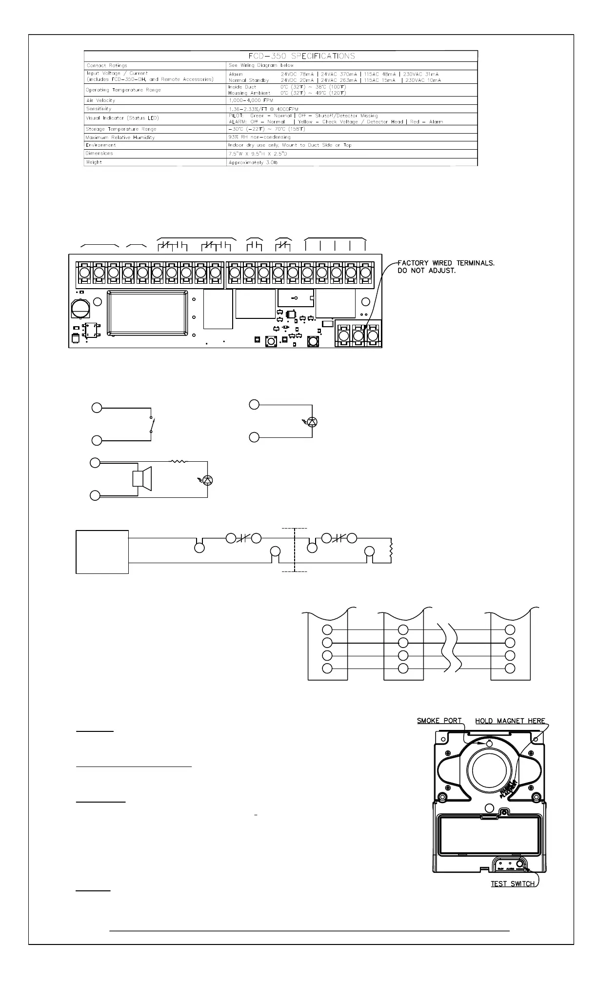
FIGURE 8. FCD-350 TEST LOCATIONS
D. WIRING DIAGRAMS
ALARM
CONTACTS
10A 115/230VAC
7A 28VDC
All contacts are shown in normal supervisory
condition. Alarm contacts will toggle during alarm
or test switch activation. Trouble contacts will
toggle to trouble condition if detector is removed.
Alarm contacts must be reset by pressing the reset
switch after activation.
REMOTE
ACCESSORIES
TROUBLE
CONTACTS
10A 115/230VAC
7A 28VDC
ALARM
CONTACTS
0.5A 115VAC
1A 24VDC
05/22
* Individual Remote Pilot LED's must be installed to monitor detector head or power source removal for each unit.
19
18
ALARM
STROBE/
HORN
Positive
Negative
ALARM
LED
i. REMOTE ACCESSORY WIRING
ii. FIRE ALARM CONTROL PANEL WIRING
iii. COMMON FUNCTION WIRING
19
18
17
UL LISTED
FIRE ALARM
CONTROL
UNIT
+
-
FCD-350 #1
FCD-350 DETECTOR
#1
12
INTERNALLY
LIMITED
20mA, 24 VDC
Negative
Positive
16
20
19
17
Key or
Push Button
"Test/Reset"
Switch
PILOT
LED
FCD-350 #30
EOLR
END
OF
LINE
RESISTOR
19
17
18
FCD-350 #2
13
14
12
15
FCD-350 DETECTOR
#2 or END
15
14
13
19
17
18
REMOTE COMMON TEST/RESET
REMOTE COMMON ALARM
REMOTE COMMON AUX POWER
COMMON AUX GROUND
INTERNALLY
LIMITED
20mA, 24VDC
20 20 20
1 2 3 4 5 6 7 8 9 10 11 12 13 14 15 16 17 18 19 20
24VAC 60Hz/
24VDC INPUT
115~230 VAC
60Hz INPUT
G N L + -
Up to 30 units may be interconnected for all alarm relays to
operate with a single alarm. Terminals 17 and 19 are optional
E. TESTING THE INSTALLATION
24 VDC
Bosch Security Systems, B.V.
*
FCD-350 Installation Instructions (HA-06-445. P/N 1700- 12670, Page 2 of 2)

 Loading...


