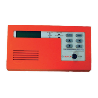
34 en Remote Keypad FMR-5000
F.01U.029.078 | 5.0 | 2009.11 Bosch Sicherheitssysteme GmbH
Notes
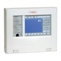
Functional Description
The Remote Keypad can be used to perform the same operating procedures as the control panel, enabling variable
operation of a networked system. It has the following functional elements (see Figure 1, III, Page 5):
Installation
Follow the mounting instructions according to the mouting variant for your application.
X Before mounting the housing, remove the operating unit. This prevents the touch screen being damaged and
facilitates installing the lower mounting screws.
Wiring
X Connect the shield wires to the screw terminal, see Figure 11, Page 14 (step 1).
X Fasten the cables with cable ties, see Figure 11, Page 14 (step 1 to 4).
The Remote Keypad has
- two CAN interfaces (CAN1/CAN2) to enable system networking (bus or loop topology), see Figure 14, Page 17
- two signal inputs (IN1/IN2)
- Ethernet, USB and RS232 interfaces
When connecting to the USB and RS232 interface, observe the maximum cable length of 3 m (see Figure 10,
Page 13).
Address Setting and Configuration
Assign a unique physical address to each Panel Controller and Remote Keypad by setting the rotary switches and
write it down on the label (see Figure 13, Page 16, step 1 and 2).
For configuration, set the 6-pin DIP switch (see Figure 13, Page 16, step 3). Mark the setting on the provided label
(step 4).
On pages 17 to 25, you will find the different types of network topologies with the required DIP switch and address
settings.
NOTICE!
Installation must only be performed by authorized and specialized personnel!
Refer to Figure 1 on Page 5 for the information on the scope of delivery.
WARNING!
Live components and stripped cable! Risk of injury from electric shock. The system must be
current-free during connection work.
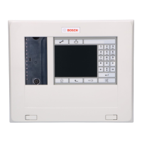
Pos. Designation Function
A Touch screen Operating the networked system through virtual buttons and variable display windows
B 22 fixed buttons Standard entries
C 11 LEDs Indicating the operating status
D Key switch 2 switch settings, freely programmable, e.g. for switching between day/night mode or
connecting/disconnecting for local alarm signaling
E Reboot button Remote Keypad HW reset
F 6-pin DIP switch Configuration
G 3 rotary switches Address setting
Mounting variants Illustration Mounting Instructions
Surface wall mounting See Figure 2, Page 6, I See Figure 3, Page 7 to Figure 5, Page 9 (step 1 to 13) and
Figure 6, Page 10
Flush wall mounting See Figure 2, Page 6, II See Figure 3, Page 7 to Figure 5, Page 9 (step 1 to 13) and
Figure 7, Page 11
Tilted installation See Figure 2, Page 6, III See Figure 3, Page 7 to Figure 5, Page 9 (step 1 to 13) and
Figure 8, Page 12
 Loading...