-5-
Maintain tools. Check for misalignment
or binding of moving parts, breakage of
parts and any other condition that may
affect the operation. If damaged, repair
tool before use. Many accidents are caused
by poorly maintained tools.
Use the tool, accessories, etc., in
accordance with these instructions and
in the manner intended for the particular
type of tool, taking into account the
working conditions and the work to be
performed. Use of the tool for operations
different from those intended could result in a
hazardous situation.
Service
Have your tool serviced by a qualified
repair person using only identical
replacement parts. This will ensure that the
safety and accuracy of the tool is maintained.
Develop a periodic maintenance schedule
for tool. When cleaning a tool be
careful not to disassemble any portion
of the tool since internal components
may be misplaced or pinched or
may be improperly mounted. Certain
cleaning agents such as gasoline, carbon
tetrachloride, ammonia, etc. may damage
plastic parts.
SAVE THESE INSTRUCTIONS.
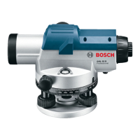
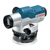
This tool is intended to quickly determine and check level points for any construction job.
Intended Use
This manual includes specifications for the
GOL Series auto level.
Verify the calibration of the
instrument. Before initial
use, follow the test shown in the section
“Line-of-sight.”
After doing any job using any instrument, it is
advised that you check your work. To check
your work, set up the instrument in a different
location from the place where you originally
set up (approx. 16 m) and reshoot a few of
your original targets. The new readings shou -
ld agree with the first readings.
If the new readings do not agree, you should
have the instrument checked by a Bosch
Authorized Repair Center, or try the Line-of-
sight adjustment.
Preparation
The numbering of the product features shown
refers to the illustration of the tool on the
graphic page 2.
1 Base Plate
2 Horizontal Circle
3 Horizontal Circle Reference Mark
4 Compensator Lock
5 Focusing Knobs
6 Optical Peep Sight
7 Sunshade / Objective Lens
8 Horizontal Drive Screw
9 Leveling Screw
10 Circular Bubble Vial
11 Vial Sighting Prism
12 Eyepiece Cover
13 Eyepiece Focusing Knob
Features
!
WARNING
 Loading...