Do you have a question about the Bosch HBLP651RUC and is the answer not in the manual?
Critical safety steps to perform before commencing any service work.
Recap of key functional and technical updates in the oven series.
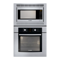
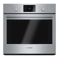
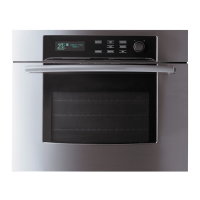
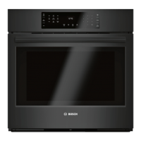
Details on model nomenclature, types, and available configurations.
Information on locating unit data plates and understanding warranty terms.
Minimum and maximum allowable temperatures for each cooking mode.
Details on elements used per cooking mode and their operational duty cycles.
Explanation of the self-clean cycle process and cooling fan functionality.
Lists components accessible from the front, side, rear, and top of the oven.
Steps for removing, reinstalling, and servicing bottom-hinge doors.
Steps for removing, reinstalling, and aligning side-hinge doors.
Procedure for replacing the motorized door latch assembly.
Instructions for resetting and replacing the oven's high-temperature cutout.
Procedures for replacing the front panel assembly and display module.
Steps for replacing oven cavity light bulbs and lamp receptacles.
Service procedures for convection fan, ring element, and motor.
Instructions for replacing the broil and bake heating elements.
Procedure for replacing the oven's temperature sensor.
Steps for replacing the main control module or daughter board.
Instructions for replacing the oven's cooling fan assembly.
Steps to remove and replace the oven's hinge receivers.
Details on oven error codes, their causes, and suggested repair actions.
How to access and utilize the oven's service mode for diagnostics and settings.
Instructions for using fault trees to diagnose and troubleshoot specific oven problems.
A key that identifies wire colors and their corresponding conductors.
Diagrams illustrating the electrical circuit paths for oven heating elements.
Information on accessing additional technical documents via QuickFinder.
Contact details and operating hours for Bosch technical support.
| Style | double |
|---|---|
| Color | stainless steel |
| Total Capacity | 4.6 cu. ft. per oven |
| Temperature Probe | yes (upper cavity) |
| Microwave | no |
| Convection | european; both |
| Control Type | digital |
| Interior Light | yes |
| Kitchen Timer | yes |
| Power Consumption | 9, 125 watts; 3800 |
| Voltage | 240/208 volts |
| Frequency | 60 hz |
| Current | 40 amps |
| Depth | 23 1/2 inch |
|---|---|
| Height | 52 1/16 inch |
| Width | 30 inch; 29 3/4" |
| Net Weight | 261.0 lbs. |