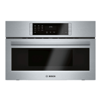
This document serves as a comprehensive service manual for Bosch Speed Microwave Ovens, specifically addressing the HMC54151UC model. It is intended for use by qualified service personnel only, emphasizing the complexity of the appliance and the inherent risks of high-voltage electrical shock, thus discouraging customer self-service. The manual contains confidential and proprietary information, restricting unauthorized review, use, copying, disclosure, or distribution.
The manual begins with a critical section on safety, highlighting that repairs must be performed by a qualified electrician due to potential hazards like live housing and frame if the appliance is faulty. It warns against touching any internal modules, as they can be live, and mandates disconnecting the appliance from the power supply before any repair work. For live testing, the use of a residual-current-operated circuit-breaker is essential. The importance of maintaining the protective conductor connection to standard values for personal safety and appliance function is stressed. Upon completion of repairs, a test in accordance with VDE 0701 or national regulations, a function test, and a leak rate test are required.
Under the "Caution!" section, the manual provides instructions to prevent damage to the appliance or its components. These include complying with ESD instructions, avoiding random component replacement, and always following systematic troubleshooting procedures. A stern warning is given against testing the high-voltage circuit while the appliance is running, reiterating the danger of death. Crucially, the high-voltage capacitor must always be discharged before any testing.
A significant part of the safety section is dedicated to the "Leak test (leak detection measurement)," which measures the microwave energy escaping despite intact sealing systems. This leak rate is quantified as an energy density in mW/cm² at a distance of 5 cm, adhering to VDE regulation 0700/Part 25. For normal operation with a load (275 cm³ water at maximum power setting), the permitted limiting value is 5 mW/cm². For abnormal, no-load operation (no load at maximum power setting), the permitted limiting value is 10 mW/cm². Illustrations are provided to show the measurement setup for both scenarios.
The "Components" section details the high-voltage diode, high-voltage capacitor, high-voltage transformer, magnetron, and safety switches. The high-voltage diode can be tested like a standard diode using an EHG tester, expecting full continuity in the conducting direction and infinite resistance in the blocking direction when set to insulation resistance. The high-voltage capacitor is tested via 'ohmic' measurement (resistance measurement range 20 MΩ). A correctly functioning capacitor shows transient continuity, with resistance increasing proportionally with the load. A defective capacitor (e.g., short-circuit) indicates permanent continuity, and the measuring instrument must show infinite resistance between the connection and housing. The high-voltage transformer supplies heater voltage for the magnetron (approx. 3.3 V) and operating voltage for voltage doubling (approx. 2300 V), with an input voltage of 230 V. The manual explicitly states that the operating voltage cannot be measured.
The magnetron is also tested by 'ohmic' measurement. The volume resistance of terminals F and FA should be less than 1 Ω, and the insulation resistance between the two terminals and the housing should be infinite. An EHG tester is used for this measurement. A critical note explains that an internal flashover (short-circuit between cathode and anode) is usually not detectable by measurement but becomes apparent when high voltage is applied, potentially through loud humming noises. Proper installation of the magnetron, ensuring the metal seal is intact and correctly seated, is emphasized to prevent microwave energy escape.
The "Safety switches" section explains that microwave ovens typically have at least three safety switches, supported by switch brackets, designed to interrupt microwave generation when the door is opened. One of these is a short-circuit switch, which monitors the other two and activates the appliance's safety device if a monitored switch fails. If this occurs, the appliance is disconnected from the power supply and cannot be switched on. A table illustrates the switching sequence: when the door is opened, the safety switch on the right, then the safety switch on the left, and finally the short-circuit switch are actuated. When the door is closed, the sequence is reversed.
The "Repair" section provides step-by-step instructions for removing various components.
- Removing the door: The door is opened, "HOLDERS" are inserted into hinge recesses, the door is carefully closed, and then lifted out of the hinge thrust bearings. After re-installation, ensuring safety switches function normally is crucial.
- Removing the bottom heating system: This involves removing the housing, discharging the HV capacitor, taking out the turntable, disconnecting the heating system, unscrewing it from the bottom and right, and then sliding and lifting it out.
- Removing the turntable motor: The metal plate is removed, the turntable shaft is carefully pried out with a flat screwdriver, the appliance is placed on its back, and the motor cover (punched into the base plate) is removed with side cutters. The motor is then disconnected, screws attaching it to the cooking compartment are removed, and after repair or replacement, the cover is screwed back to the base plate.
- Removing the cooling fan: The housing is removed, the HV capacitor discharged, the H.V. diode unscrewed, the magnetron disconnected, and the fan motor disconnected. The cooling fan assembly is then unscrewed and removed, followed by unscrewing and removing the fan retaining plate.
- Removing the upper heating elements: This involves removing the housing, discharging the HV capacitor, unscrewing and lifting out the cooling fan assembly, disconnecting the magnetron and H.V. transformer, then unscrewing and removing them. The wiring above the upper heat protector assembly is disconnected, the assembly unscrewed from the cavity upper plate and carefully lifted out. The heating elements are disconnected, hex nuts on the right side and upper part of the cavity are removed, and finally, the upper heating elements are lifted out.
- Removing the hot air motor: The housing is removed, the HV capacitor discharged, and the rear cover removed. The hot air assembly is disconnected, the oven sensor removed, and the hot air assembly carefully unscrewed and lifted out. The hot air motor is disconnected, the hex nut attaching the inner fan blade to the motor shaft is removed, and the inner fan blade is pulled out. The hot air motor bracket is unscrewed, and the hot air motor with the bracket is lifted out, followed by removing the outer fan blade. Finally, the hot air fan motor is unscrewed from its bracket.
- Removing the magnetron: The housing is removed, the HV capacitor discharged, the magnetron TCO removed, and the magnetron disconnected. The left air guide is removed, and the magnetron is unscrewed. A critical note advises ensuring fastening screws are tightened during re-installation to prevent microwave energy escape and that there is no gap between the hollow conductor and the magnetron.
The "Fault Diagnostics" section provides detailed troubleshooting plans for various issues.
- Troubleshooting plan - fuse is tripping: This flowchart guides technicians through checking the short-circuit switch when the door is closed. If there's continuity, the switch is defective and needs replacement. If no continuity, the fuse is replaced. Then, the safety switch is checked when the door is opened. Continuity indicates a defective safety switch requiring replacement. No continuity leads to removing one cable between the transformer and high-voltage capacitor and switching on the appliance. Normal function suggests a defective high-voltage capacitor, while a tripping fuse points to a defective high-voltage transformer. Both defective components require replacement along with the fuse.
- Troubleshooting plan - appliance does not function at all: This expands on the fuse tripping scenario, adding checks for the magnetron's "clicking" safety device and the mains cable. If the fuse is not tripping, and the magnetron's safety device shows no continuity, it's defective and needs replacement. If there's continuity in the mains cable check, but the appliance still doesn't function, the mains cable is deemed defective and needs replacement.
- Troubleshooting plan - appliance does not start: This flowchart addresses issues where the set time does not count down after starting. It directs checking the safety switch (on the left) when the door is closed. No continuity indicates a defective switch needing replacement. Continuity leads to checking the cable between the relay board and the switch. No continuity here suggests a defective relay board, while continuity indicates a loose connection cable that needs to be secured.
- Troubleshooting plan - no microwave power: This plan starts by checking the power relay during function. No continuity points to a defective relay board. Continuity leads to checking the high-voltage transformer and HV fuse. If not OK, they are defective and need replacement. If OK, the high-voltage capacitor is checked. If not OK, it's defective and needs replacement. If OK, the high-voltage diode is checked. If not OK, it's defective and needs replacement. If OK, the magnetron is checked. If not OK, it's defective and needs replacement.
- Troubleshooting plan - input module: This section lists several statuses indicating a potentially defective input module: incomplete display segments (missing, partial, or flickering), non-displayed or flashing comma/decimal point, slight brightness variation, non-illuminating characters, display not counting down or increasing in clock mode, time display jumping during countdown, display counting down too quickly, no display symbols after cooking cycle selection, no time display at the end of cooking, and no acoustic signal when buttons are pressed. A flowchart further details troubleshooting for input issues. If no input can be programmed, the connection between the button system and board is checked. No continuity indicates a board defect, while continuity suggests a loose connection. If some inputs cannot be programmed, using a different button system is suggested. If functions then work as anticipated, the original button system is defective. If the fault persists, the board is defective. Other symptoms like the display showing a different number/symbol than input, random programming, or a frozen display with no further inputs are all attributed to a defective board.
- Troubleshooting plan - Error Codes of input module: This section provides a table of error codes and their explanations: E1 (Thermistor open), E2 (Safety time), E3 (Damper function failed), E4 (Thermistor short), and E17 (Preheat fail). Each error code description includes the condition for detection and the subsequent appliance behavior (e.g., reverting to plug-in mode, remaining off until a button is pushed).
Finally, the manual outlines a procedure for "Determining the microwave output power (Pab)." This involves heating a specific volume of cold tap water using two microwave-proof utensils (each 1 liter capacity) and a thermometer with an immersion sensor. The steps are: determine initial temperature (mean value), cook for 2 minutes at maximum power, determine end temperature (mean value), calculate the temperature difference, and then calculate the output power using the provided formula: (TB - TA) x 70 + 100 = Pab [watts], where TA is the initial temperature and TB is the end temperature.