CABINET CONSIDERATIONS AND COUNTERTOP CUTOUT
Dimension requirements in Figs. I
& 2 are for combustible surfaces.
When the surface is protected by a
material listed by UL as a Floor
Protector and Wall Shield and is
covered with not less than No. 28
MSG sheet metal, 0.015-inch
stainless steel, or 0.024-inch
aluminum or copper, it is considered
noncombustible and some
dimensions may be reduced. For a
noncombustible surface over the
cool<top, the minimum clearance is
24" rather than 30".
Instructions are based on
standard American cabinets 36"
high x 24" deep with a 25"
countertop.
Provide approximately a 10-
square-inch opening in the toe
kid< area or other cabinet area
for adequate air inlet to the
cabinet.
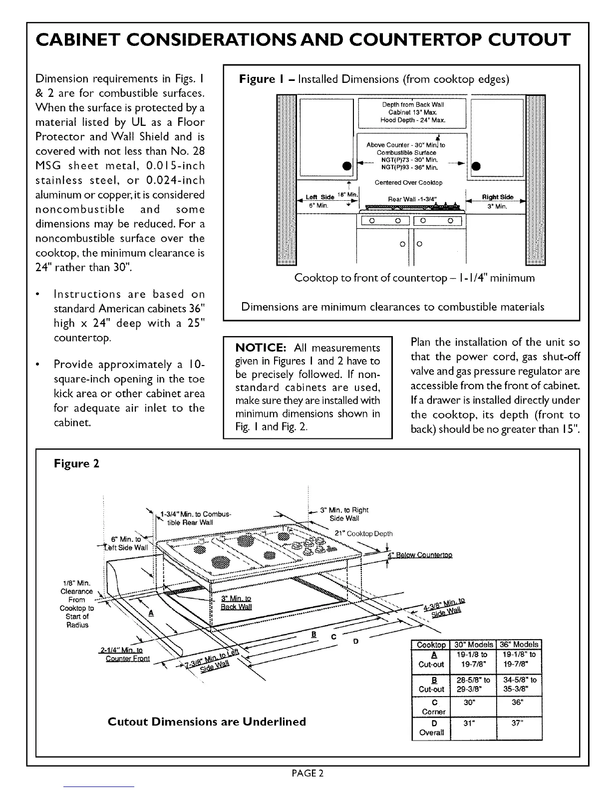
Figure I - Installed Dimensions (from cool<top edges)
Depth from Back Wall
Cabinet !3" Max.
Hood Depth - 24" Max.
Above Counter - 30" Min_to
Combustible Surface
• _ NGT(P)73- 30" Min. . _.
NGT(P)93 - 36" Min. •
÷ Centered Over Cooktop
Left Side 18_"" Rear Wall *1-3/4"
_-M_n. '_ ._ Right Side
3" Min.
Io o IIo o I
0 0
Cool<top to frontofcountertop - I-I/4"minimum
Dimensions are minimum clearances to combustible materials
NOTICE: All measurements
given in Figures I and 2 have to
be precisely followed. If non-
standard cabinets are used,
make sure they are installed with
minimum dimensions shown in
Fig. I and Fig. 2.
Plan the installation of the unit so
that the power cord, gas shut-off
valve and gas pressure regulator are
accessible from the front of cabinet.
Ifa drawer is installed directly under
the cool<top, its depth (front to
bad<) should be no greater than 15".
Figure 2
1-3/4" Min, to Combus-
tible Rear Walt
_3" Min, to Right
Side Wail
21" Cooktop Depth
1/8" Min.
Clearance
From
Cooktop to
Start of
Radius
2-1/4" Min. to "_
Cutout Dimensions are Underlined
30" Models 36" Models
A ' 19-1/8 to 19-1/8" to
Cut-out 19-7/8" 19-718"
B 28-5/8" to 34-5/8" to
Cut-out 29-3/8" 35-3/8"
C 30" 36"
Corner
D 31" 37"
Overall
PAGE 2