Replacement procedure for INV PCB
Split ODU – 6 720 817 722 (2015/06)
40
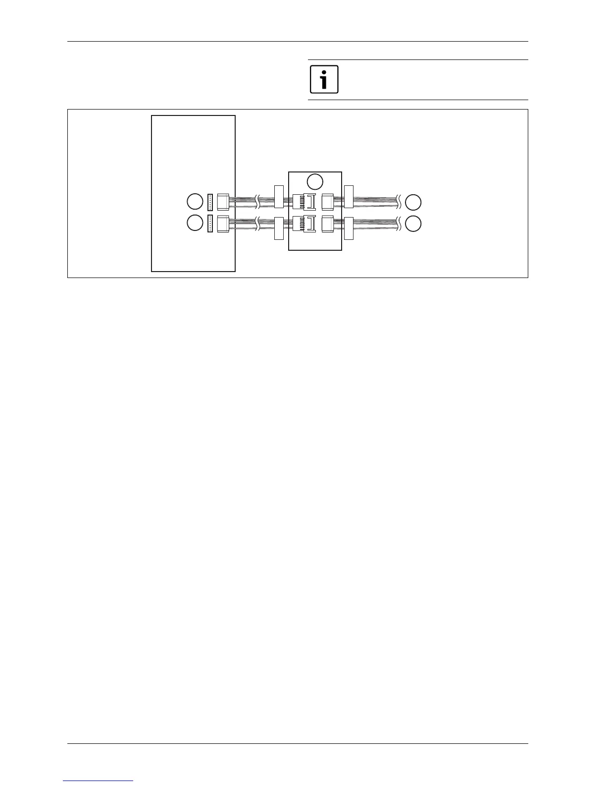
Fig. 39 INV PCB fan motor connection
[1] Fan motor wire terminal (UP)
[2] Fan motor wire terminal (DOWN)
[3] Main PCB case
[4] To Fan motor
[5] To Fan motor
Attention! After replacing the INV PCB assembly, make
sure that connection of the fan motor wires is correct.
YELLOW
RED
YELLOW
RED
YELLOW
RED
YELLOW
RED
INV. PCB
UP
DOWN
UP
DOWN
2
3
1
5
4
6 720 817 722-40.1I