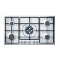
DON'Ts DOs
Do not place receptacles on
burners off centre. They
could tip over.
Do not use wide-based re-
ceptacles on the burners
nearest to the controls.
When centred on the bur-
ner, they could touch the
controls or raise the tempe-
rature in the area. This may
damage the hob.
Do not place receptacles
directly on top of burners.
Do not use excessive weig-
hts or strike the hob with
Handle receptacles on the
care
.
Warnings concerning cooking:
Do not use receptacles with
uneven bases. They leng-
then cooking times and in-
Only use thick-,flat-based
frying pans
Do not cook without lids or
with lids only partially cove-
ring receptacles. You are
wasting energy.
Always use lids.
Always place recepta-
in the middle of
Always place receptacle
Make sure that the metal
grids and the tops of the
burners are correctly posi-
tioned before using them.
Do not cook without lids or
with lids only partially cove-
ring receptacles. You are
Do not use receptacles with
uneven bases. They leng-
then cooking times and in-
Do not place receptacles on
burners off centre. They
Do not use wide-based re-
ceptacles on the burners
nearest to the controls.
When centred on the bur-
ner, they could touch the
controls or raise the tempe-
rature in the area. This may
Do not place receptacles
directly on top of burners.
Do not place receptacles
directly on top of burners.
Do not use excessive weig-
hts or strike the hob with
Do not use small recepta-
cles on large burners. The
flame should not touch the
sides of receptacles.
Always use suitably sized
receptacles on each bur-
ner. This helps avoid ex-
cessive gas consumption
and prevents receptacles
from getting tarnished.
Do not use two burners or
heat sources for a single
Do not use baking trays,
earthenware dishes, etc...
at full heat for a long time
Only use one recipient per
burner. Use the extra
saucepans,
and casseroles.
cles
burners.
crease energy consumption.
on the pans support.
hob with
heavy objects.
recipient.
.
burner.
17
metal grid on the wok
61,8
915
45
Installation
Before connecting the unit, check whether the local
connection conditions (type of gas) are compatible with
the unit’s setting. Observe any special conditions imposed
by local suppliers (utilities). The specifications of this
cooktop are stated on the data label located on the
bottom of the cooktop base.
an accessible location near the hotplate if the data
A duplicate data label is supplied for adhesion to
accessed when the hotplate is installed.
label on the base of the hotplate cannot be
1
Gas inlet
connection
1a
Gas inlet
connection
61,8
915
520
45
min.50
490
600
850
+
-
1
+
-
1
520-530
min.50
490
600
850
+
-
1
+
-
1
45
490
27
880
45
490
27
min. 100
min. 100
880
Pressure
test point.
130
Pressure
test point
80
Natural gas connection
Universal LPG
Pressure
test point.
130
Pressure
test point
80
Natural gas connection
Universal LPG
This installation must conform with the following:
• Manufacturer’s Installation instructions
• Local Gas Fitting Regulations
• Municipal Building Codes,
• AGA Installation Code for Gas Burning Appliances.
• S.A.A. Wiring Code
• Local Electrical Regulations
• Any other statutory regulations
These built-in hobs are intended to be inserted in a
benchtop cutout.
Only an officially authorised technician should connect
the appliance.
Preparing to
install
Installation dimensions are shown in Fig.1.
(AS 5601 - 2004 - Gas Installations).
Statutory
requirements
Refer to the AGA Installation Code for piping size details.
Before you begin, turn off the gas and electricity supply.
min 30 / max 60
min 30 / max 60
6