English | 15
Bosch Power Tools 1 609 92A 0BR | (14.10.13)
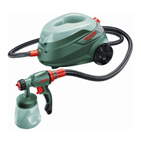
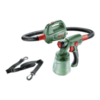
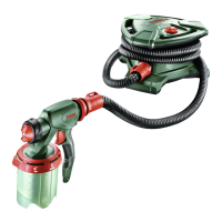
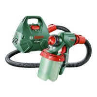
11 Nozzle
12 Nozzle seal
13 Air hose
14 SDS connector
15 Base unit
16 Control knob for On/Off and air-flow control
17 Set-down port for spray gun
18 Hose connection (base unit)
19 Handle
20 Accessory compartment
21 Air filter cover
22 Measuring cup
*Accessories shown or described are not part of the standard de-
livery scope of the product. A complete overview of accessories
can be found in our accessories program.
Technical Data
Noise/Vibration Information
Measured sound values determined according to EN 60745
and EN 50580.
Typically the A-weighted sound pressure level of the product
is 74 dB(A). Uncertainty K=3 dB.
The noise level when working can exceed 80 dB(A).
Wear hearing protection!
Vibration total values a
h
(triax vector sum) and uncertainty K
determined according to EN 60745:
a
h
< 2,5m/s
2
, K= 1,5 m/s
2
.
The vibration level given in this information sheet has been
measured in accordance with a standardised test given in
EN 60745 and may be used to compare one tool with another.
It may be used for a preliminary assessment of exposure.
The declared vibration emission level represents the main ap-
plications of the tool. However if the tool is used for different
applications, with different accessories or insertion tools or is
poorly maintained, the vibration emission may differ. This may
significantly increase the exposure level over the total working
period.
An estimation of the level of exposure to vibration should also
take into account the times when the tool is switched off or
when it is running but not actually doing the job. This may signif-
icantly reduce the exposure level over the total working period.
Identify additional safety measures to protect the operator
from the effects of vibration such as: maintain the tool and the
accessories, keep the hands warm, organisation of work pat-
terns.
Declaration of Conformity
We declare under our sole responsibility that the product de-
scribed under “Technical data” is in conformity with the fol-
lowing standards or standardization documents: EN 60335
and the directives 2011/65/EU, 2006/42/EC,
2004/108/EC including their amendments.
Technical file (2006/42/EC) at:
Robert Bosch GmbH, PT/ETM9,
D-70745 Leinfelden-Echterdingen
Robert Bosch GmbH, Power Tools Division
D-70745 Leinfelden-Echterdingen
Leinfelden, 18.10.2013
Assembly
Before any work on the machine itself, pull the mains
plug.
Connecting the Air Hose (see figures A1 – A2)
– Take the air hose 13 out of the accessory compartment 20.
– Remove the protective caps from both ends of the air hose.
Connecting to the spray gun:
– Firmly insert an SDS connector 14 of the air hose in align-
ment with the arrow mark into the hose port of the spray
gun 6.
– Turn the SDS connector until the lock engages.
Connecting the base unit:
– Firmly insert the second SDS connector of the air hose in
alignment with the arrow mark into the port of the base
unit 18.
– Turn the SDS connector until the lock engages.
Note: After use, reattach the protective hose caps to the hose
ends.
Operation
Preparing for Operation
Spraying on the sides of water bodies (lakes, rivers,
etc.) or neighbouring surfaces in the direct catchment
area is not permitted.
When purchasing paint, varnish and spray material, pay at-
tention to their environmental compatibility.
Fine-spray System PFS 105 E
Article number
3 603 B06 2..
Rated power input
W 350
Spraying capacity
g/min 150
Atomising output
W 0 –105
Required time for application
of paint on 5 m
2
min 6
Container capacity for spray
material
ml 800
Length of air hose
m3,4
Weight according to
EPTA-Procedure 01/2003 kg 4,9
Protection class
/II
The values given are valid for a nominal voltage [U] of 230 V. For differ-
ent voltages and models for specific countries, these values can vary.
Henk Becker
Executive Vice President
Engineering
Helmut Heinzelmann
Head of Product Certification
PT/ETM9
OBJ_BUCH-420-003.book Page 15 Monday, October 14, 2013 2:59 PM