Do you have a question about the Bosch PFS 105 and is the answer not in the manual?
Essential safety precautions for operating power tools, covering workplace, electrical, and personal safety aspects.
Specific safety instructions for fine-spray systems, focusing on preventing fire, explosion, and injury.
Details the types of materials suitable for spraying and those that are not.
Lists and describes the numbered components of the fine-spray system.
Provides detailed technical specifications for the PFS 105 E fine-spray system.
Details measured sound and vibration levels according to EN 60745 standards.
States conformity with relevant EU directives and standards.
Step-by-step guide on how to connect the air hose to the spray gun and base unit.
Covers preparing the unit, starting, switching on/off, and general operational procedures.
Provides guidance on spraying techniques, distance, pattern, and capacity adjustments.
How to adjust the spray pattern using the air cap and union nut.
How to adjust the amount of spray material using the thumbwheel.
How to adjust the air flow and pressure using the control knob.
Guidelines for cleaning the spray gun and its components to ensure proper function.
Instructions on how to replace a soiled air filter.
Troubleshooting guide for common problems and their corrective measures.
Provides contact details for service and support in various regions.
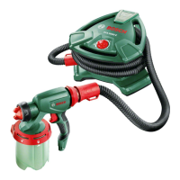
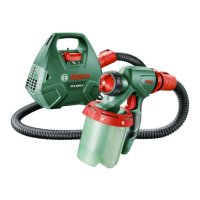
This document describes the Bosch PFS 105 E fine-spray system, a power tool designed for atomizing various solvent-based and water-dilutable materials.
The Bosch PFS 105 E is a fine-spray system intended for applying paints, finishes, primers, clear finishes, automotive finishes, staining sealers, wood sealer-preservatives, plant protectives, oil, and disinfection agents. It operates by drawing material from a container and atomizing it through a nozzle using an air-flow system. The device is not suitable for spraying dispersions and latex paint, caustic solutions, acidic coating materials, coating materials with granules or solids, or spray and drip-impeding materials.
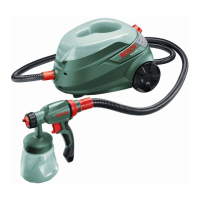
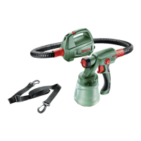
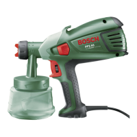
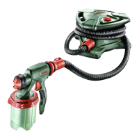
The system consists of two main parts: a spray gun and a base unit. The spray gun holds the material container and features an air cap, union nut, thumbwheel for spraying capacity, trigger switch, suction tube with container seal, nozzle, and nozzle seal. The base unit houses the motor and controls, including a control knob for On/Off and air-flow control, a set-down port for the spray gun, a hose connection, a handle, an accessory compartment, and an air filter cover. An air hose connects the spray gun to the base unit, delivering air for atomization.
The device is designed for a nominal voltage of 230 V, but can also be operated with 220 V. Hearing protection is recommended during operation due to noise levels potentially exceeding 80 dB(A).
Assembly and Preparation: The air hose (13) is stored in the accessory compartment (20) and must be connected to both the spray gun (6) and the base unit (18) using SDS connectors (14). Protective caps should be removed before connection and reattached after use. The base unit must always be placed horizontally on a level and clean surface during operation to prevent drawing in dust or contamination.
Material Preparation: Users must observe the information on drums/tanks/tins and manufacturer information for the spray material, including safety warnings and personal protective equipment requirements. The spray surface must be clean, dry, and grease-free. Smooth surfaces should be roughened, and sanding dust removed. When diluting spray material, a measuring cup (22) is used, and the material is stirred thoroughly. A 10% dilution with paint thinner is a common starting point, followed by a test-spray run to ensure the desired pattern. The suction tube (10) in the container (8) should be oriented towards the front for horizontal spraying or towards the rear for overhead spraying to minimize residue.
Operation: To switch on, the control knob (16) on the base unit is turned to the right, preferably starting with maximum air flow. The trigger switch (9) on the spray gun is then pulled. Air continuously flows from the nozzle (11) when the base unit is on. To switch off, release the trigger switch (9) and turn the control knob (16) to the left. The spray gun can be placed in the set-down port (17) for transport or when idle.
Spraying Technique: A test-spray run is recommended to adjust the spray pattern and material quantity. The spray gun should be held vertically to the spray object at a uniform clearance of 5–15 cm. Spraying should begin and end outside the target area. Paths should overlap by 4–5 cm for an even surface quality. Interruptions within the spray surface should be avoided. Uneven clearance or spray angle can lead to heavy paint mist and an uneven surface. The container should not be sprayed completely empty to prevent an uneven spray jet.
Adjustments:
Cleaning (Figures I-K): Thorough cleaning of the spray gun and container is essential for flawless operation and to maintain warranty validity. The spray gun and container should be cleaned with the respective diluting agent (paint thinner or water). The complete spray gun should never be immersed in cleaning agent. The nozzle (11) and air holes should not be cleaned with pointed metal objects. Diluted spray material should not be returned to the original drum for storage.
Cleaning steps include:
Changing the Air Filter (Figure L): The air filter should be replaced when soiled. To do this, remove the air filter cover (21), change the filter, and remount the cover.
Troubleshooting: A table of common malfunctions, their causes, and corrective measures is provided. For example, if spray material does not cover properly, the spraying capacity may be too low (correct by turning thumbwheel 5 in direction IIII), or the material may be too viscous (correct by thinning it down). If no spray material emerges, the control knob (16) may be too far to the left (correct by turning it to the right), or the container (8) may have no pressure build-up (correct by screwing it firmly against the spray gun).
Material Disposal: Diluting agents and remainders of spray material must be disposed of in an environmentally-friendly manner, observing manufacturer's disposal information and local regulations for hazardous waste. Chemicals harmful to the environment should not be disposed of into soil, groundwater, or bodies of water, nor poured into sewerage systems.
Service: For repairs, the machine should be serviced by a qualified repair person using identical replacement parts. The 10-digit article number from the type plate should always be included in correspondence and spare parts orders. Bosch provides after-sales service and customer assistance through various regional centers.
| Brand | Bosch |
|---|---|
| Model | PFS 105 |
| Category | Paint Sprayer |
| Language | English |