Do you have a question about the Bosch Rexroth ctrlX I/O XI312204 and is the answer not in the manual?
Covers signal type, input range, conversion time, resolution, accuracy, and protection.
Details dimensions, weight, electrical isolation, EMC, mounting, and approvals.
Provides the product type and part number for ordering.
Lists general specifications like number of inputs and connection method.
Details terminal assignments and LED indicators for channels.
Covers temp, humidity, protection, and warnings on contamination/overheating.
Specifies intended use, user qualifications, and safety precautions.
Explains signal processing steps and distinct values/data formats.
Details standard and module-specific CoE objects for parameterization.
Outlines the different mechanisms used for module diagnostics.
Provides guidance on connecting analog inputs, cables, and shielding.
Covers ESD precautions, mounting location, end clamps, and support rails.
Guides on physical mounting, safety notices, and connector engagement.
Warns against dismounting powered, and details removal from support rail.
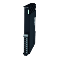
The ctrlX I/O Analog Input Terminal XI312204 is a crucial component for processing analog signals within a ctrlX I/O station. This 4-channel module is designed to handle input signals ranging from 0 to 10 V, digitizing them with a high resolution of 16 bits. A key feature of this terminal is its galvanic isolation, which ensures that the digitized signals are safely transferred to the system level, protecting sensitive components from electrical interference. Each of the four input channels operates differentially, enhancing signal integrity and noise immunity.
The primary function of the XI312204 terminal is to convert incoming analog voltage signals into digital data for use within the ctrlX I/O system. This process begins with the analog input signal being fed into the module, where it undergoes filtering by a first-order low-pass filter to limit the frequency range before reaching the analog-digital converter (ADC). The filtered signal is then digitized by the ADC with a 16-bit resolution, including sign. The module supports an "Oversampling" feature, which, when enabled, allows the ADC to sample multiple values and transmit their average. This functionality helps to restrict the effective useful signal frequency, improving data quality.
The module also incorporates a robust signal processing chain, which includes hardware components for low-pass filtering and oversampling, as well as firmware functions for other processing steps. This ensures accurate and reliable signal conversion. The digitized data is then transferred to the control system via the local bus. The terminal is designed to integrate seamlessly into the parent system, with respective ESI files available for configuration.
Diagnostic capabilities are built into the XI312204. Error states are clearly indicated by LEDs located on the removable peripheral connector for each channel. These error states are also routed to the control system via the local bus, allowing for prompt identification and resolution of issues. The module's logic and peripheral voltage supply, as well as its EtherCAT-based communication, are managed through the module itself.
The "User Scale" functionality is a significant feature that allows for individual correction of both the gain (User Gain) and the offset (User Offset) for each channel. This enables users to fine-tune the module's response to specific input ranges, effectively mapping a desired input range to a corresponding output range. This adjustment can be configured in the "Pre-Op" state and should be written upon each start of the EtherCAT bus via the start parameter.
The module also performs limit value checks on the ADC input data, determining if values are above or below the valid range. Status bits such as "Overrange," "Underrange," or "Wire break" are set in the process data accordingly, providing immediate feedback on signal integrity. These limits are configurable and contribute to the module's diagnostic capabilities.
The XI312204 is designed for ease of use and integration within the ctrlX I/O ecosystem. Its compact dimensions (12 mm width, 105 mm height, 99 mm depth) and light weight (95 g including connector) make it suitable for various installation scenarios. The module supports a 2-wire, shielded, twisted pair connection method, ensuring reliable signal transmission.
Mounting the module is straightforward, as it is designed for vertical installation on a horizontal support rail. The push-in connection method for the inputs simplifies wiring. For optimal performance and safety, it is recommended to use shielded cables twisted in pairs for analog sensors and to connect the cable shielding to functional earth immediately after entering the control cabinet.
The module's parameterization can be configured channel-granularly via ctrlX Works (start parameter), eliminating the need for manual address or configuration settings. This simplifies setup and commissioning. The module's status is indicated by a multi-color LED, providing visual feedback on its operational state, including booting, initialization, process data transmission, and error conditions. Each input channel also has its own status LED, signaling signal errors like overrange, underrange, or wire breaks.
For electrical connections, the module supports one-wire cables and stranded cables with or without wire end ferrules. The allowed cable cross-section is between 0.25 mm² and 1.5 mm² (AWG 24 to 16), with a stripping length of 8 mm. For stranded cables without ferrules, twisting the strand between 180° and 360° is recommended.
The XI312204 incorporates several features that facilitate maintenance and troubleshooting. The module's diagnostic strategy includes EtherCAT state machine diagnostics, an EtherCAT hardware watchdog, and diagnostic objects accessible via the CoE object directory. This comprehensive approach allows for extended diagnostics, including peripheral errors.
The diagnosis history object (10F3hex) acts as a ring memory, storing the latest 20 diagnostic messages. This historical data is invaluable for identifying intermittent issues and understanding the sequence of events leading to a fault. Error settings can also be configured, and the module status LED provides a general overview of the module's health.
The channel status LEDs on the plug provide immediate visual indication of signal errors, such as overrange, underrange, or wire breaks, for each individual channel. This allows maintenance personnel to quickly pinpoint the source of a problem without needing to access the control system. The diagnostics for "Wire break" can be run channel-granularly and can be switched off for individual channels if not required.
For physical maintenance, the module is designed for easy removal from the support rail using a slotted screwdriver. It is crucial to disconnect the module and all connected components from voltage before mounting or dismounting to prevent electrical damage. The module's robust design, including EMC resistance compliant with EN 61000-6-2 and EN 61000-6-4, ensures reliable operation in industrial environments.
Proper installation notes, such as ensuring sufficient distance for cooling and using end clamps to secure the module on the support rail, contribute to the longevity and trouble-free operation of the device. The module's design also emphasizes protection against electrostatic discharge (ESD) during operation, aligning with EN 61340-5-1 standards.
| Input Channels | 16 |
|---|---|
| Voltage Range | 24 V DC |
| Protection Class | IP20 |
| Series | ctrlX |
| Communication Interface | Ethernet |