SSB 6720892984 (2019/02) US
Service reminder | 65
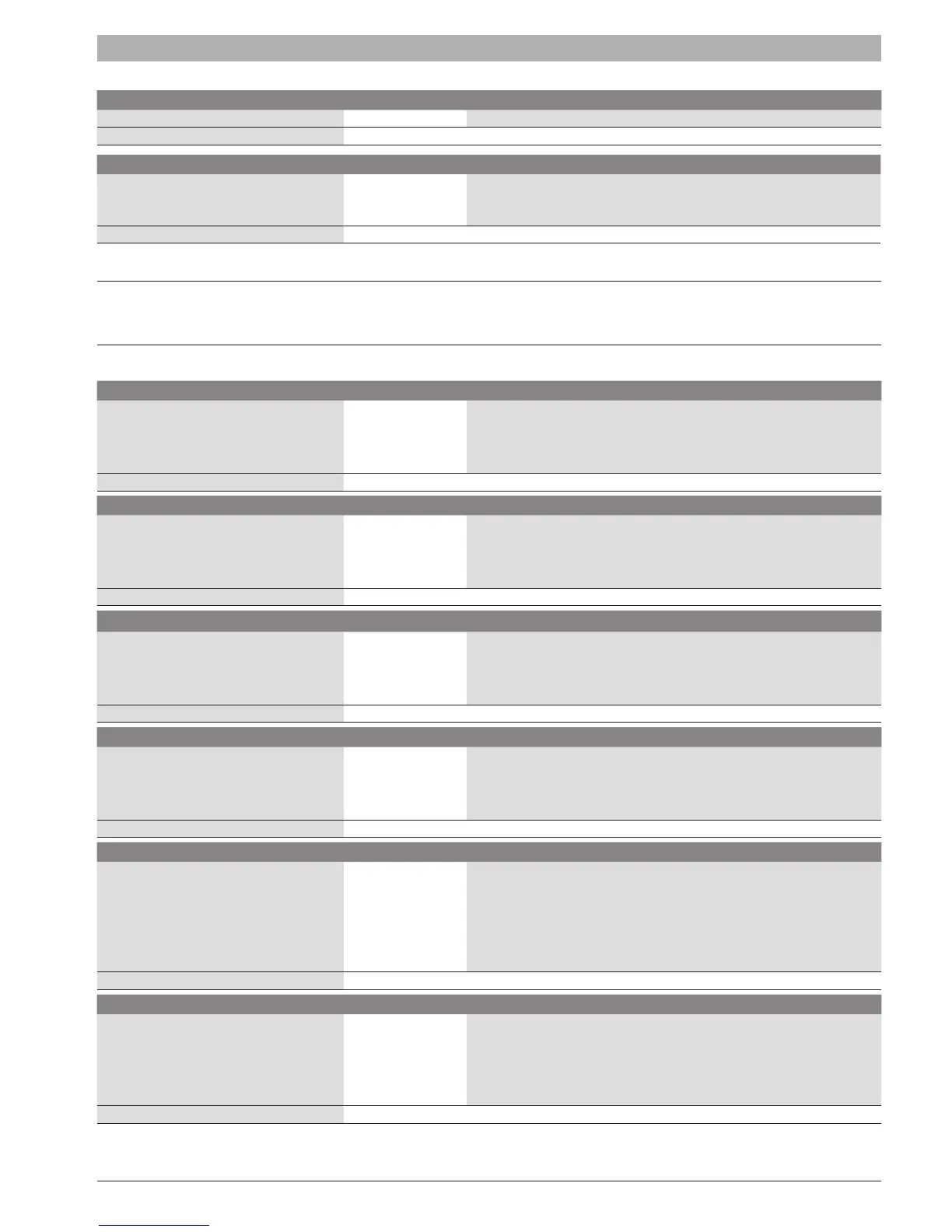
Connector Pin Pin Description
J7 1 Spark Return
SPARK RETURN
Connector Pin Pin Description
T1 1
High voltage output (spark plug).
Within this connection a 1K series resistor must be present close to the spark
plug.
IGNITION TRANSFORMER
Appendix J - PB Connectors Description
J.1 900PB06_3R
Connector Pin Pin Description
J3
Mini Combicon,
MCV 1,5-2-G-3,81 (top entry header)
1
2
AL-BUS 1
AL-BUS
AL-BUS INTERFACE
Connector Pin Pin Description
J1, J6, J7 (all three Not Placed)
Mini Combicon,
MCV 1,5-2-G-3,81 (top entry header)
1
2
AL-BUS 1
AL-BUS 2
AL-BUS INTERFACE
Connector Pin Pin Description
J4 (Not Placed)
Molex Mini-Fit Jr. 5566
Receptacle 1x2 (top entry header)
1
2
AL-BUS 1
AL-BUS 2
AL-BUS INTERFACE
Connector Pin Pin Description
J5 (Not Placed)
Molex Mini-Fit Jr. 5569
Receptacle 1x2 (side entry header)
1
2
AL-BUS 1
AL-BUS 2
AL-BUS INTERFACE
Connector Pin Pin Description
J21 (or J22 - Not Placed)
Molex Mini-Fit, Receptacle 2x3
J21: 5569 (side entry header)
J22: 5566 (top entry header)
1
2
3
4
5
6
AL-BUS 1
GND
Modbus B/1
AL-BUS 2
24V
Modbus A/+
CONNECTION TO MN CONTROL/MODBUS
Connector Pin Pin Description
J24 (or J23 - Not Placed)
Molex Micro-Fit, Receptacle 2x4
J24: 43045DRVP-4 (top entry header)
J23: 43045DRP-4 (side entry header)
1
2
3
4
9V
Communication
24V
GND
COMMUNICATION WITH 900 CONTROL




 To Next Page