EasyManua.ls Logo

Bosch UT-L 1 User Manual

Bosch UT-L 1
88 pages
To Next Page IconTo Next Page
Page #1 background imageLoading...
Page #1 background image
Technical guide
Heating boiler
UNIMAT
UT-L
6 720 807 794(2013/04)EN

Table of Contents

Question and Answer IconNeed help?

Do you have a question about the Bosch UT-L 1 and is the answer not in the manual?

Bosch UT-L 1 Specifications

General IconGeneral
BrandBosch
ModelUT-L 1
CategoryBoiler
LanguageEnglish

Summary

1 Oil/gas special boilers

1.1 Types and heating output

Boiler output range and low-pressure hot water specifications.

1.2 Overview of models

Table detailing boiler sizes and specifications.

1.3 Possible applications

Applications like hospitals, industrial plants, district heating.

1.4 Features and benefits

Highlights 3-pass design, compact construction, low emissions, economic viability, operational reliability.

2 Basic principles

2.1 Basic principles of condensing technology

Explains net/gross calorific values and efficiency above 100%.

2.1.2 Boiler efficiency above 100%

How condensing boilers achieve >100% efficiency using gross calorific value.

2.2 Making optimal use of condensing technology

2.2.1 Matching to the heating system

Importance of system design temperatures for condensation heat utilisation.

2.2.2 High standard seasonal efficiency [to DIN]

2.2.3 Design information

2.3 Economic viability considerations

3 Technical description

3.1 UNIMAT UT-L boiler

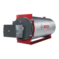
Overview of the UNIMAT UT-L boiler, covering its features and function.

3.2 UNIMAT UT-L boiler

3.2.1 Version overview

Describes different versions of the boiler, including heat exchanger options.

3.2.2 Function principle

3.3 Dimensions and specification for the flue gas heat exchangers

3.3.1 UNIMAT UT-L boiler

Table providing main dimensions for UNIMAT UT-L boilers.

3.3.2 Integrated heat exchanger without condensing technology – ECO 7

3.3.3 Integrated heat exchanger with condensing technology – ECO6

3.3.4 Stand-alone flue gas heat exchanger without condensing technology – ECO 7

3.3.5 Stand-alone flue gas heat exchanger with condensing technology - ECO 6

3.4 Connections

3.4.1 Flow and return

Table of internal diameters for flow and return connections.

3.4.2 Flue outlet connection

Table of flue outlet connection diameters by rated output.

3.4.3 Connector

3.5 Characteristics

3.5.1 Pressure loss on the water side

Graph showing water side pressure loss vs. flow rate.

3.5.2 Pressure loss on the hot gas side

3.5.3 Combustion chamber volume load

3.5.4 Boiler efficiency, standard seasonal efficiency [to DIN] and standby loss

Boiler efficiency and standard seasonal efficiency [to DIN]

Definitions and formulae for boiler efficiency.

Standby loss

3.5.5 Flue gas temperature

4 Burner

4.1 General requirements

Requirements for oil and gas burners.

4.2 Information on burner selection

Guidelines for selecting a suitable burner.

4.3 Matched pressure-jet burners

Importance of matching boiler and burner for optimal combustion.

4.4 Combustion details for the UNIMAT UT-L boilers

Burner attachment limit

Table of burner attachment dimensions.

5 Regulations and operating conditions

5.1 Extracts from the regulations

Overview of boiler compliance with EN 303, TRD 300, and DIN-EN 12828.

5.2 German Immissions Act (BlmSchG)

5.2.2 Information on flue gas tests pursuant to BlmSchV/TA Luft

5.3 Operating requirements

5.3.1 Operating conditions

Warranty conditions for minimum flow rate, return, and design temperatures.

5.3.2 Fuel

Approved fuels and requirements for gas and oil.

5.3.3 Corrosion protection in heating systems

Measures to prevent corrosion on the boiler water side.

5.3.4 Corrosion protection if system out of use for long periods

5.3.5 Guidelines for water quality

5.3.6 Minimum requirements of water analyses for designing a water treatment system

6 Sound pressure level from noise in the boiler system

6.1 Sound emissions from the boiler system

Sources of noise in a boiler system.

6.2 Noise in the installation room

Factors affecting noise levels in the installation room.

6.3 Noise at the chimney outlet

Noise transmitted to the chimney and reduction methods.

7 Boiler control and control system

7.1 CFB 810 control unit with CME 930 auxiliary module

Application and safety functions of the CFB 810 control unit.

7.2 CFB 930 and CFB 910 control units

7.3 Side control unit holder

7.4 UNIMATIC display units and control units

7.5 BCO boiler control

8 DHW heating

8.1 Systems for DHW heating

Boiler use for central DHW heating with cylinders.

8.2 DHW temperature control

Control of DHW temperature using CFB system.

9 System examples

9.1 Information regarding all system examples

Introduction to system examples and hydraulic connections.

9.1.1 Hydraulic connection

9.1.2 Control system

9.1.3 DHW heating

9.1.4 Pipework schemes

9.2 Safety equipment to DIN-EN 12828

9.2.1 Requirements

Safety equipment installation according to DIN EN 12828.

9.2.2 Layout of safety components to DIN-EN 12828

Schematic of safety components for direct heating.

9.2.3 Safety equipment for the flue gas heat exchanger

9.2.4 Maximum operating flow temperatures

9.3 Sizing and installation information

9.3.1 Boiler circuit pump in the bypass as shunt pump

Hydraulic circuit for boiler circuit pump as shunt.

Calculating the flow rate of the boiler circuit pump

Heating circuit flow rate VHK

Total boiler flow rate VKges

9.3.2 Boiler circuit pump as primary circuit pump

Boiler circuit pump flow rate VPK

Formulae for estimating boiler circuit pump flow rate.

Head of the primary circuit pump

Factors determining primary circuit pump head.

9.3.3 Hydraulic balancing line

Sizing the low loss header

How to size a low loss header correctly.

9.4 1-boiler system with UNIMAT UT-L boiler: boiler and heating circuit control unit

9.5 1-boiler system with UNIMAT UT-Lboiler: boiler and heating circuit control unit with hydraulic separation

9.6 1-boiler system with UNIMAT UT-L boiler: boiler circuit control unit

9.7 1-boiler system with UNIMAT UT-L boiler: boiler circuit control unit with hydraulic separation

9.8 2-boiler system with two UNIMAT UT-L boilers: boiler circuit control unit with hydraulic separation

9.9 1-boiler system with UNIMAT UT-L boiler with flue gas heat exchanger: boiler circuit control unit

9.10 1-boiler system with UNIMAT UT-L boiler with condensing heat exchanger: boiler circuit control unit with hydraulic separation

9.11 2-boiler system with UNIMAT UT-L boiler without flue gas heat exchanger and UT-L boiler with condensing heat exchanger: boiler circuit control unit with hydraulic separation

9.12 UNIMAT UT-L boiler with flue gas heat exchanger or condensing heat exchanger: return temperature raising

10 Fitting

10.1 Transport and handling

Delivery methods and handling procedures for boilers.

10.1.2 Handling dimensions

Minimum dimensions for handling and transport.

10.2 Design of installation rooms and combustion air supply

10.2.1 Installation location

General requirements for boiler installation rooms.

10.2.2 Combustion air supply

Requirements for combustion air supply and apertures.

10.3 Installation dimensions

10.3.1 Installation room dimensions for the UNIMAT UT-L boilers

Installation room dimensions for standard boilers.

10.3.2 Installation room dimensions for the UNIMAT UT-L boilers with flue gas heat exchanger

10.4 Additional safety equipment to DIN-EN 12828

10.4.1 Safety equipment

Standard safety equipment versions.

10.4.2 Boiler safety equipment assembly to DIN-EN 12828

Components of boiler safety equipment assembly.

10.4.3 Intermediate return piece

10.4.4 Safety valve

10.4.5 Flash trap to DIN-EN 12828

10.4.6 Return flow temperature safeguard set (maintaining version)

10.5 Additional devices for sound insulation

10.5.1 Requirements

Necessity and scope of sound insulation measures.

10.5.2 Flue gas silencer

Reducing noise via flue gas silencers.

10.5.3 Burner silencer hoods

Attenuating burner noise with silencer hoods.

10.5.4 Boiler mounts to attenuate structure-borne noise

Using boiler mounts to reduce structure-borne noise.

10.5.5 Boiler foundation

10.6 Further accessories

10.6.1 Drain connection and blow-down valve assembly

Recommended drain connection for quick draining.

10.6.2 Walk-on boiler cover

Optional walk-on boiler cover with ladder and safety rail.

11 Flue system

11.1 Requirements

General notes and formulae for flue system sizing.

11.1.1 General notes

General notes for flue system sizing.

12 Condensate drain

12.1 Condensate

Creation of condensate from fuel combustion.

12.1.2 Condensate disposal

Routing and neutralising condensate.

12.2 Neutralising system NE 2.0

Installation and equipment of the NE 2.0 neutralising system.

Related product manuals