WH17, WH27, WH36 AE115, AE125, (FD108 and higher) | 3
|
Data subject to change without notice | Printed in the USA | BTC 722002309 B | 05.2014
Bosch Thermotechnology Corp.
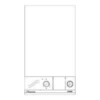
Flow
Transducer
w
Tr
ns
cer
Figure 3
Step 4 – Verify the power supply
Check the power supply using an appropriate scale for 240 VAC.
1. Measure the incoming voltage:
― WH17 / AE-115 have two readings (Fig. 4)
― WH27 / WH36 / AE-125 have three readings (Fig. 5)
2. Check the pairing of the incoming power connections by
measuring the voltage of all combinations of L1 to L1 and
L2 to L2. Voltage between any of these pairs (L1-L1 or L2-
L2), indicates an installation error and must be resolved by
an electrician.
2 independent 40 amp double-pole
circuit breakers
17kW terminal block
To Supply 2
To Supply 1
Supply 1
Supply 2
2 in
epen
ent 40 amp
ou
e-po
circ
it
re
ker
17kW termin
l
l
c
o Supp
y 2
o Supp
1
upp
y 1
upp
Figure 4
27kW - 3 independent 40 amp double-pole circuit breakers
36kW - 3 independent 60 amp double-pole circuit breakers
27/36kW terminal block
To Supply 1
To Supply 2
To Supply 3
Supply 2
Supply 1
Supply 3
7kW - 3 inde
endent 40 am
double-
ole circuit breaker
6kW - 3 inde
endent 60 am
double-
ole circuit breaker
27
36kW terminal bloc
o Supp
1
o Supp
y 2
o Supp
y
uppl
2
Supp
Supp
Figure 5
3. Check that voltage is reaching the PCB by measuring the
voltage between the blue and brown power connections
on the board itself (Fig. 6).
Figure 6
PCB power connections
(brown / blue wires)
Heater bottom
4. Shut off the circuit breakers powering the appliance, lock
them, and verify that there is no voltage at the unit.
5. Document your fi ndings in the Water Heater questionnaire.
 Loading...