36 720 607 884
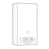
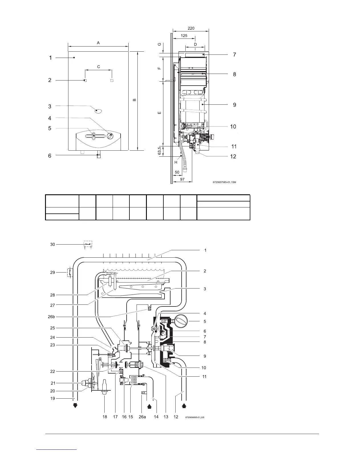
1.4 Dimensions
Fig. 2
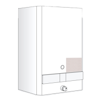
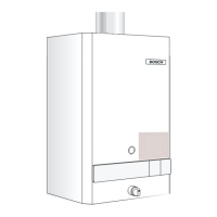
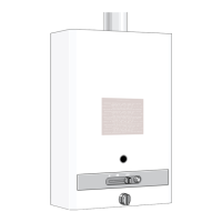
1.5 Appliance design
Fig. 3
1. Heat exchanger
2. Main burner
3. Injector
4. Slow ignition valve
5. Temperature control
6. Venturi
7. Adjusting screw for min. water flow rate
8. Water valve
9. Water throttle
10. Water filter
11. Membrane
12. Cold water pipe
13. Magnetic unit
14. Gas supply pipe
15. Gas filter
16. Regulating screw
17. Pilot filter
18. Piezo
19. Hot water pipe
20. Output control
21. Igniter button
22. Main gas valve
23. Gas valve for pilot burner
24. Pilot burner injector
25. Gas valve
26a. Testing point for supply pressure
26b. Testing point for burner pressure
27. Thermocouple
28. Igniter electrode
29. Temperature limiter
30. Flue gas safety device
1. Front cover
2. Hole for fixing to wall
3. Observation window
4. Temperature control
5. Output control
6. Gas connection
7. Exhaust pipe union
8. Draught diverter with flue
gas monitor
9. Heat exchanger
10. Automatic gas valve
11. Piezo
12. Water valve
 Loading...