52
Disassembly Procedures
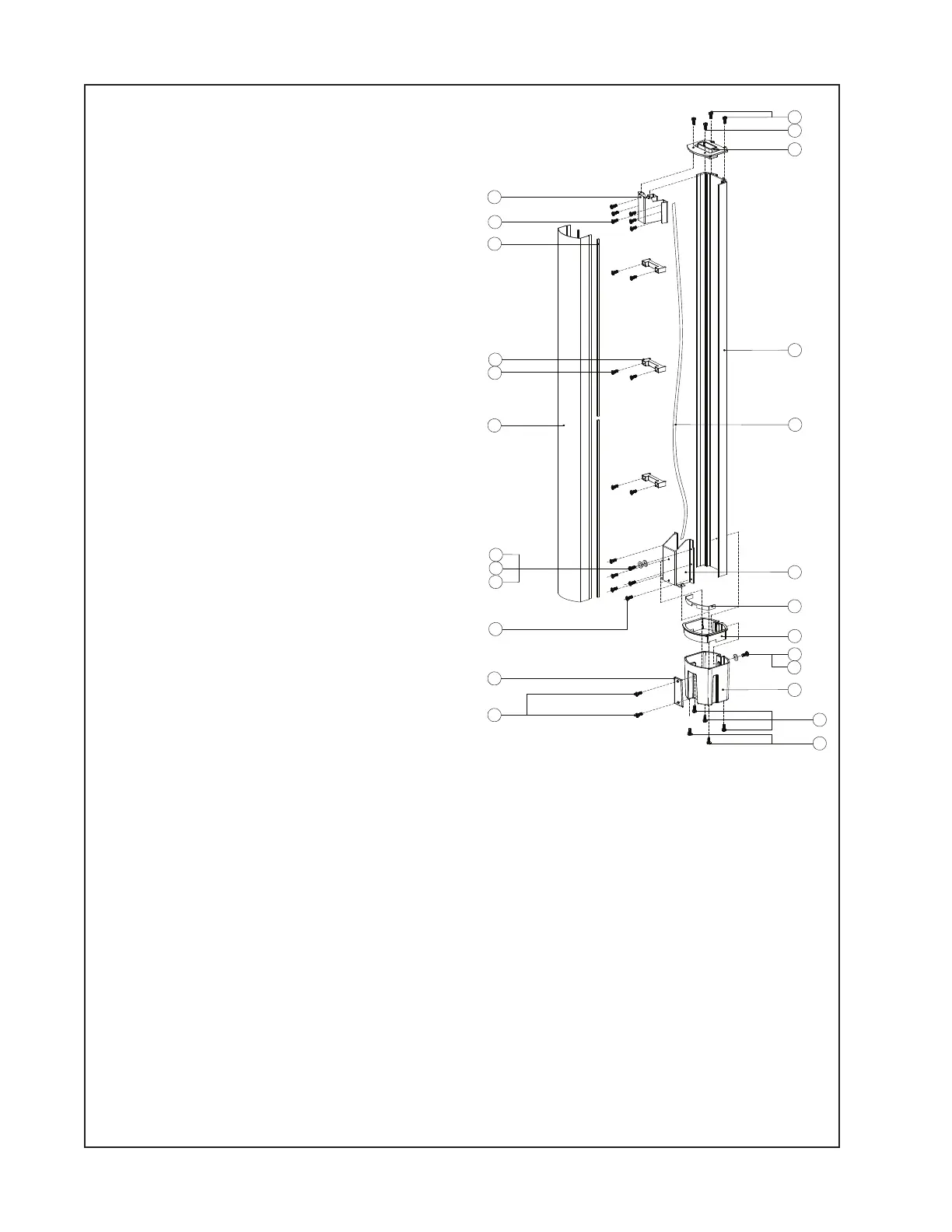
3. Array Extension Front Cover Removal
3.1 Remove the four screws (1,2) that
secure the end cap # 3 (top end cap) assem-
bly to the line array enclosure (4). Lift off the
end cap. Do not unplug the molex connector
from the speaker harness. Be sure to use
the correct screw type in the proper location
during re-assembly.
3.2 Remove the two screws (2) that secure
the teflon strip (12) to the front of the end
cap # 4 (bottom end cap) assembly. Lift off
the teflon strip. Remove the four screws that
secure the end cap # 4 assembly to the
array extension enclosure. Slide off the end
cap (11). Do not unplug the molex connector
from the speaker harness. When re-installing
the end cap # 4 assembly, be sure that the
green/yellow ground wire is routed through
the notch in the steel bottom plate.
3.3 Grasp the edge of the extension cover
(17) and gently lift it away from the enclo-
sure.
4. Driver Removal
Note: Refer to the line array exploded view
diagram on the previous page for this proce-
dure.
4.1 Perform procedure 1.
4.2 Remove the four screws (3) that secure the driver (4) to the driver baffle (5).
4.3 Lift the driver out of the baffle. Unplug the wires from the driver terminals. Be sure to
observe polarity when installing the new driver.
Note: Refer to the line array exploded view diagram on the previous page for procedures 5 & 6.
5. Line Array Top End Cap (# 1) Removal
5.1 Remove the fours screws (1,13) that secure the end cap (14) to the line array enclosure
(16). Lift off the end cap.
6. Line Array Bottom End Cap (# 2) Removal
6.1 Remove the fours screws (1,13) that secure the end cap (12) to the line array enclosure
(16). Lift off the end cap. Unplug the molex connector from the speaker harness.
21
13
20
3x 19
6x 18
17
16
15
14
11x 13
12
2
2
1
11
10
9
8
7
6
5
4
3
2 x6
1 x5
 Loading...