53
Disassembly Procedures
Note: Refer to the array extension exploded view diagram on the previous page for
procedures 7 & 8.
7. Array Extension Top End Cap (# 3) Removal
7.1 Remove the fours screws (1,2) that secure the end cap (3) to the line array enclosure (4).
Lift off the end cap. Unplug the molex connector from the speaker harness.
8. Array Extension Bottom End Cap (# 4) Removal
8.1 Remove the two screws (2) that secure the teflon strip (12) to the front of the end cap # 4
assembly. Lift off the teflon strip. Remove the four screws (1,2) that secure the end cap # 4
assembly to the array extension enclosure (4). Slide off the end cap. Unplug the molex
connector from the speaker harness.
Re-assembly Note: When re-installing the end cap # 4 assembly, be sure that the green/yellow
ground wire is routed through the notch in the steel bottom plate.
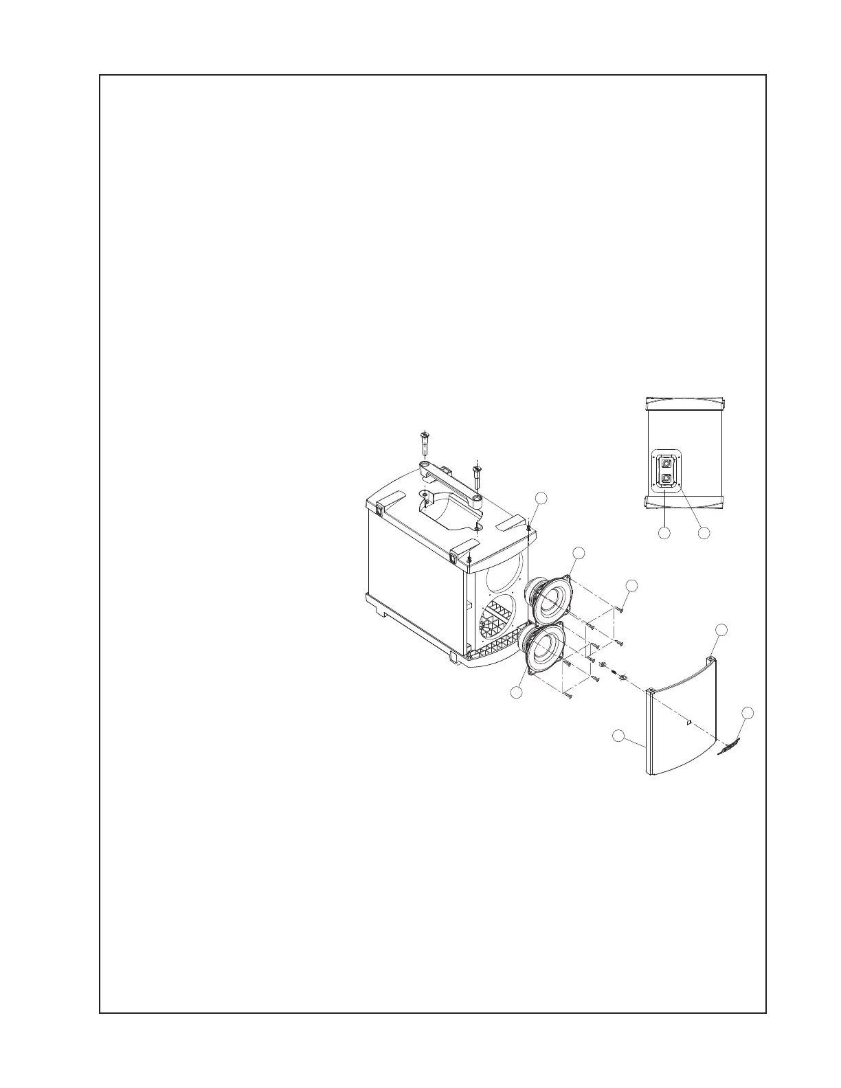
B1 Bass Module Procedures
Refer to the figure at right for the
following procedures.
1. Grille Removal
1.1 Remove the four allen screws
(1) that secure the grille (5) to the
upper and lower speaker end
caps. Lift off the grille.
2. Bose
®
Logo Removal
2.1 Perform procedure 1.
2.2 On the back of the grille (5),
remove the retaining nut and
spring from the post of the logo
(7). Lift the logo off of the grille.
3. Woofer Removal
3.1 Perform procedure 1.
3.2 Remove the four screws (4) that secure the woofer (2) to the bass module enclosure.
3.3 Lift the woofer out of the enclosure. Note the wiring configuration and unplug the wires from
the driver terminals. Be sure to observe polarity when installing the replacement woofer.
1
2
4x
2x
48x
32x
5
7
62x
8
9
 Loading...