(7) INPUTS 1–4: Analog Input Channels 1–4. Accepts XLR balanced cables for microphones or ¼-inch TRS
balanced or TS unbalanced cables for high-impedance inputs, such as guitars.
(8) DIGITAL MAIN OUTPUT L: Connect digitally in stereo to two L1® Model 1S/II systems.
Note: Only used in stereo with Digital Main Output R.
(9) POWER PORT/DIGITAL MAIN OUTPUT R: A digital output used by the L1 Model 1S/II system. Delivers
power to the T4S mixer from the L1 Model 1S/II power stand. Can also deliver power from an AC outlet via a
ToneMatch power supply (not included with the T4S). Accepts the included ToneMatch® cable.
CAUTION: Although the ToneMatch port accepts a standard RJ-45 connector, do NOT connect the
T4S to a computer or phone network.
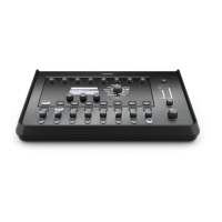
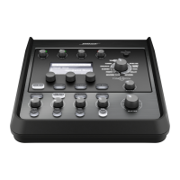
T8S ToneMatch® Mixer
Control Panel
Figure 3. T8S Control Panel
(1) INPUT SIGNAL/CLIP LEDs (1–8): Displays the input signal status in color:
Green: Indicates the presence of an input signal
Red: Indicates input source clipping
(2) TRIM CONTROLS (1–8): Adjusts the input sensitivity for the respective channel.
(3) DISPLAY: Provides function menus and system information.
(4) EDITING CONTROLS: These three rotary/push-button controls allow you to select or adjust items/values
appearing on the display.
(5) CH EDIT BUTTONS (1–8): Selects the channel you want to modify.
(6) FX MUTE BUTTONS (1–8): Bypasses the Mod, Delay, and Reverb effects on the selected channel.
(7) VOLUME CONTROLS (1–8): Adjusts the volume level for the respective channel.
(8) MUTE BUTTONS (1–8): Silences the audio output for the respective channel.
(9) MASTER VOLUME CONTROL: Adjusts the overall output level.
(10) HEADPHONE VOLUME CONTROL: Adjust the volume level of the headphone output.
(11) STEREO OUTPUT METER: Allows you to visually measure your output level.
(12) ROTARY SELECTOR: Allows access to both global and channel-related parameters, which are adjusted
using the editing controls.
(13) PHANTOM POWER SWITCH: Applies +48V power to Input Channels 1–8. A red LED indicates that
phantom power is on.
CAUTION: Set the Master volume control to its minimum position before using the phantom power
switch or powering on/off any microphones that use phantom power.
(14) HEADPHONE JACK: For use with headphones only, with a minimum impedance of 24 Ω.
Connection Panel
Figure 4. T8S Connection Panel