Do you have a question about the Boss Audio Systems CHAOS CH700 and is the answer not in the manual?
| Brand | Boss Audio Systems |
|---|---|
| Model | CHAOS CH700 |
| Category | Car Amplifier |
| Language | English |
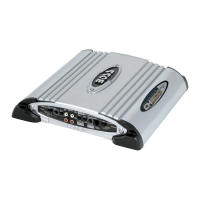
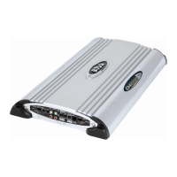
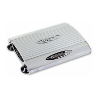
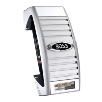
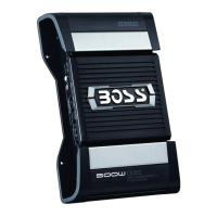
Specifies the maximum power output at 2 Ohms for the amplifier, 600W x 2 channels.
Details the RMS power output at 200W x 2 channels, indicating continuous power delivery.
States the bridged power output as 1200W x 1 channel for mono operation.
Indicates the range of audio frequencies the amplifier can reproduce, from 9Hz to 50KHz.
Quantifies the level of distortion produced, at a low 0.01%.
Measures the signal-to-noise ratio at 130dB, indicating clarity of the audio signal.
Specifies the required voltage for the power source, 14.4V.
Denotes the grounding type as negative, crucial for installation.
Details the power draw at 25A with 125Wx2 rated output.
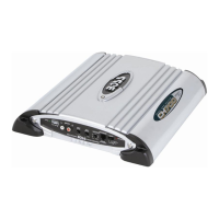
Provides the physical size of the unit: 300mm (W) x 65mm (H) x 356mm (D).
Emphasizes using only specified parts for safety and liability reasons during repair.
Stresses returning parts and wiring to their original locations to maintain circuit integrity and safety.
Advises thorough checks after repair to ensure no secondary problems or safety hazards exist.
Warns about disconnecting battery before working on automotive wiring to prevent short circuits or fires.
Provides specific advice on handling and replacing chip components, like tantalum capacitors.
Offers guidelines for soldering flexible PCBs, including iron temperature and tip application.
Instructs to turn off unit during disassembly and recheck work before applying power.