EasyManua.ls Logo

Boss RE-20 COSM User Manual

Boss RE-20 COSM
32 pages
To Next Page IconTo Next Page
Page #1 background imageLoading...
Page #1 background image
SERVICE NOTES
Issued by RJA
Copyright © 2007 ROLAND CORPORATION
All rights reserved. No part of this publication may be reproduced in any form without the written permission
of ROLAND CORPORATION.
Printed in Japan (0370) (SC-MZ)17058511E0
May, 2007 RE-20
Table of Contents
Cautionary Notes ..............................................................2
Main Specifications...........................................................3
Location of Controls .........................................................4
Location of Controls Parts List........................................5
Exploded View (1).............................................................6
Exploded View (1) Parts List...........................................7
Exploded View (2).............................................................8
Exploded View (2) Parts List...........................................9
Exploded View (3)...........................................................10
Exploded View (3) Parts List.........................................11
Parts List ...........................................................................12
Verifying the Version Number......................................16
Factory Reset....................................................................16
System Update.................................................................16
Test Mode.........................................................................16
Circuit Board (Jack Board) .............................................24
Circuit Diagram (Jack Board) ........................................26
Circuit Board (Panel Board)...........................................28
Circuit Diagram (Panel Board)......................................30
Revice Infomation
July, 18, 2008 Part Name Corrected (p. 7, p. 13)
Question and Answer IconNeed help?

Do you have a question about the Boss RE-20 COSM and is the answer not in the manual?

Boss RE-20 COSM Specifications

General IconGeneral
BypassBuffered Bypass
TechnologyCOSM
MIDINo
Effect TypeEcho
Input1/4" TRS
Output1/4" TRS
Power Supply9V DC
Weight1.2 kg
Power Source9V DC
Dimensions173 mm (W) x 158 mm (D) x 57 mm (H)

Summary

Cautionary Notes and Explanations

No User Data

Product cannot save user data; backing up during servicing is not required.

Parts List Information

Explains reasons for parts unavailability, including assembly, copyright, or order restrictions.

Circuit Diagram Conventions

Defines 'NIU' and notes circuit diagrams show silk-screened indications without components.

Main Specifications Overview

Unit Controls and Features

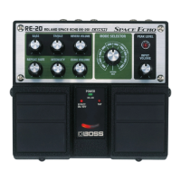
Details all physical controls on the unit, including pedals, knobs, and switches.

Indicators and Connectivity

Lists all indicator lights and specifies connector types and functions.

Electrical Characteristics

Outlines input/output levels, impedance, power supply requirements, and current draw.

Accessories and Options

Lists standard accessories and optional items like manuals and expression pedals.

Control Layout Diagram

Control Parts Identification

Exploded View Diagram (1)

Exploded View (1) Parts List

Exploded View Diagram (2)

Exploded View (2) Parts List

Exploded View Diagram (3)

Exploded View (3) Parts List

Comprehensive Parts List

Parts List by Component Category

Potentiometers, Capacitors, and Coils

Lists parts categorized as potentiometers, capacitors, coils, and filters.

Fuses, Connectors, and Wiring

Details parts such as fuses, fuse holders, connectors, and wiring/cables.

Fasteners, Packing, and Miscellaneous

Lists fasteners, packing materials, LEDs, spacers, and other small parts.

Standard Accessories List

Version Number Verification

Version Check Procedure Steps

Detailed steps to verify the unit's software version using LED indicators.

Test Mode Entry and Requirements

Lists required equipment and initial setup for entering the test mode.

Factory Reset

System Update

Test Mode Introduction

Detailed Test Procedures

Version Check and LED Tests

Steps for checking software version and LED illumination/current consumption.

Volume Control and EXP Pedal Tests

Procedures to test volume control operation and EXP pedal functionality.

Switch and Analog Bypass Tests

Maximum Amplitude Waveform Check

Analog Bypass FET Switch Test

D/A Output Waveform Verification

DSP, Noise, and Battery Tests

DSP Throughput and Noise Measurement

Tests DSP throughput waveform and measures residual/audible noise levels.

Battery Operation Verification

Procedure to confirm the unit operates correctly using battery power.

Jack Board Component Layout

Jack Board Circuit Schematic

Panel Board Component Layout

Panel Board Circuit Schematic

Related product manuals