• Particularités :
- Amplificateur auto-protégé contre les surcharges et les
court-circuits.
- Limiteur et compresseur en protection de sortie
- Sortie de puissance par transformateur
- Possibilité d’adapter une carte 18 kHz de détection de
défaut amplificateur ou de court-circuit de ligne.
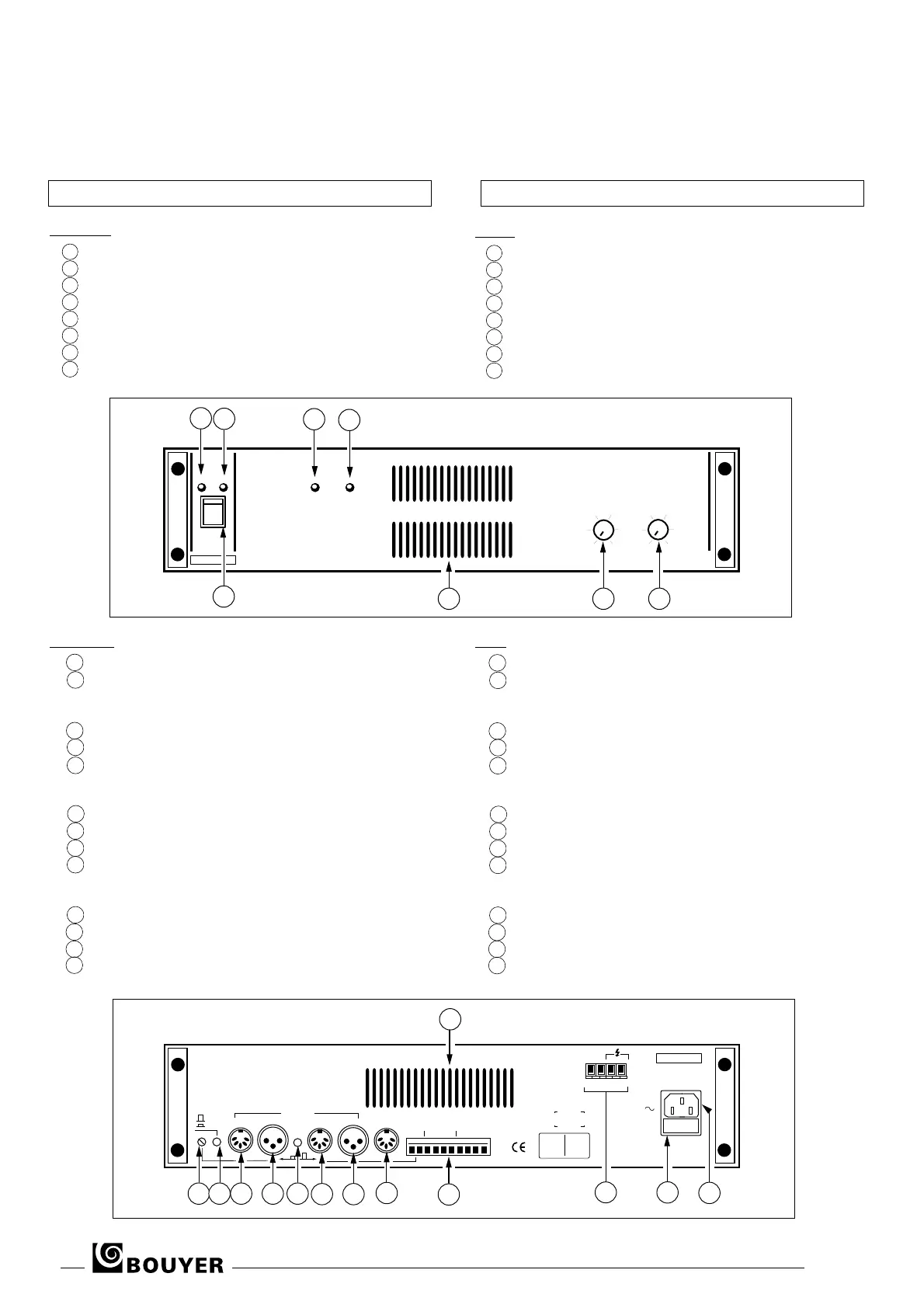
A l'avant (Fig. III)
1 - Témoin de mise sous tension
2 - Interrupteur de marché/arrêt
3 - Témoin de modulation
4 - Témoin d’écrêtage
5 - Témoin de surcharge
6 - Grille de ventilation
7 - Réglage de l’entrée 2 : AUX
8 - Réglage de l’entrée 1 : AUX/MIC
A l'arrière (Fig. IV)
9 - Préréglage entrée 1
10 - Commutation MIC/AUX entrée 1
• Position MIC - Relâché
• Position AUX - Enfoncé
11 - Entrée DIN n°1 MIC/AUX
12 - Entrée XLR n°1 MIC/AUX
13 - Commutation de priorité
• Enfoncé entrée 1 prioritaire sur entrée 2
• Relâché entrée 2 prioritaire sur entrée1
14 - Entrée DIN n°2 AUX
15 - Entrée XLR n°2 AUX
16 - Sortie DIN 0 dB
17 - Bornier de télécommande priorité des entrées
Information carte de détection de défaut (en option) et
alimentation du pupitre microphone GC 1021
18 - Bornier sortie de puissances (0 - 4Ω - 70V - 100V)
19 - Fusible (5x20) secteur
20 - Prise secteur 230V avec terre
21 - Grille de ventilation
• Particularities :
- Amplifier protected against overload and electrical leakage
- Output protection by compressor limitor
- Power output by transformer
- Possibility to adapt a 18 kHz fault detection board indicating
the failure of the amplifier or electrical leakage on line.
Front (Fig. III)
1 - ON indicator LED
2 - ON/OFF switch
3 - Modulation indicator LED
4 - Peak indicator LED
5 - Overload indicator LED
6 - Ventilation grille
7 - Input 2 (AUX) control
8 - Input 1 (AUX/MIC) control
Rear (Fig. IV)
9 - Input 1 preset MIC/AUX
10 - Input 1 commutation MIC/AUX
• MIC position unbended
• AUX position pushed
11 - DIN input n°1 MIC/AUX
12 - XLR input n°1 MIC/AUX
13 - Priority commutation
• pushed input 1 has priority on input 2
• unbended input 2 has priority on input 1
14 - DIN input n° 2 AUX
15 - XLR input n° 2 AUX
16 - DIN output 0 dB
17 - Remote control priority of inputs
Information fault detection board (optional) and
GC 1021 mic console power supply
18 - Power output terminal (0 - 4Ω - 70V - 100V)
19 - Mains fuse (5X20)
20 - Mains plug 230V with earth
21 - Ventilation grille
ON
ON Mod.
Peak
Overlead
OFF
2
1
3
5
4
AR 1402
1
0
2
4
6
8
10
2
0
2
4
6
8
10
6 7 8
Fig.
III
20
19
Fus. T5A
17
ALIM
TELECOM
PRIORIT
OPTION
OUT 0dB
1 1
2 2
ENTREES
INPUTS
PRIORIT
MIC
AUX
9
10 1311
12
14
16
15
21
230V
50/60Hz
BOUYER
SRTIES
OUTPUTS
0 4‰ 70V 100V
18
ATTENTION :
dbrancher le
secteur avant
d’ouvrir
CAUTION :
disconnect
from supply
before
opening
Fig. IV
III - PRESENTATION III - PRESENTATION
2 AR 1402
 Loading...