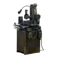
BOYAR-SCHULTZ 6-12 HYDRAULIC SURFACE GRINDER
See Boyar-Schultz instructions for the handfeed
model 6-12 surface grinder before removing the
machine from its crate. Follow instructions given
in the paragraphs describing handling, installation
and lubrication.
HYDRAULIC RESERVOIR
The hydraulic pump and the pump motor are
housed in the lower section of the hydraulic reser-
voir. The pump motor must be connected to the
starter switch. This is done by connecting the
multi-wired cable that extends from the rear of
the reservoir to the junction box located on the
back of the grinder. A four wire cable is furnished
for three phase installation. Match up loose wires
by the color code, secure each, and insulate. The
green wire should be fastened to the clamp screw
inside the junction box to complete the ground.
A three wire cable is furnished for single phase
installation. Match up color coded wires and
ground the green wires to the junction box clamp
screw.
Two hoses are furnished with the machine. The
intake hose (long hose) should be connected to the
lower of the two elbows that protrude from the
reservoir, to the front elbow, located on the right
side of the grinder carriage. The exhaust hose
(short hose) should be connected to the upper
reservoir elbow and to the rear carriage elbow. In
both cases, tighten the hose to the carriage elbows
first. Station reservoir on the floor as shown in
accompanying literature. The back of the reservoir
should be approximately flush with the back of the
grinder stand.
Remove top cover of the reservoir and add the
three gallons of hydraulic oil that are furnished
with the machine — see Lubrication Chart for
recommended oils. The level of the hydraulic oil
should not be permitted to drop below the top of
the filter screen. To insure long, trouble-free opera-
tion of this hydraulic machine, the hydraulic oil
should be changed every six months. The reservoir
and the filter screen should be cleaned at the time
of the oil change.
AUTOMATIC OPERATION
The stop dog, located on the front edge of the
grinder table, control the longitudinal travel of the
table. The stop dogs may be adjusted by means of
a 5/32" hex wrench to suit the length of stroke
desired. The dogs must be set so that the pilot
valve head (the two pronged casting located on the
top of the valve body) is located between them.
The stop dog to the right of the valve must strike
the upper arm of the pilot valve head and the stop
dog to the left must strike the lower arm. For
initial operation of the machine, the stop dogs
should be set approximately six inches apart.
Connect cylinder rod to table adapter housing.
The table adapter housing is located on the under-
side of the table at its right end. To engage the
cylinder rod, raise the pin that protrudes from the
housing and insert the ball end of the cylinder rod.
Oscillate the table handwheel while exerting a
slight downward pressure on the adapter housing
pin until the cylinder rod is locked into place.
Before operating the machine hydraulically, the
table handwheel must be disengaged. Pull out the
knob of the plunger, located on the left side of the
carriage, and pull out the handwheel. Release
plunger to lock handwheel in the "OUT" position.
CAUTION!
Check to see that the grinding wheel clears the
work and that the magnetic chuck is energized.
The starter switch is located on the right side of
the grinder base. The switch has three positions,
"MANUAL", "OFF" and "AUTO". To start
spindle and hydraulic pump motor, place switch
into the "AUTO" position. To set the table in
motion, turn the shut-off valve handle (located on
top of the valve) in the direction indicated by the
arrow.
Erratic action of the table in its initial operation
or after prolonged idleness is due to air in the
hydraulic system. The air will work out and the
action will improve after a short run-in period.
MANUAL OPERATION
Place shut-off valve in the "OFF" position and
set starter switch in the "MANUAL" position.
Manual operation of the longitudinal table feed is
simplified if the cylinder rod is disengaged from the
table. To disengage the cylinder rod, raise the pin
that protrudes from the adapter housing and move
the table to the right, allowing the pin to drop after
the cylinder rod is clear of the adapter housing.
Cylinder rod disengagement is recommended only
when prolonged manual use is anticipated.
TABLE CUSHION ADJUSTMENT
A needle valve adjustment has been provided
on the right side of the main valve to cushion the
table reversals. To adjust, loosen the lock nut and
screw the needle valve in to increase or out to
decrease the cushion.
This adjustment has been made at the factory
and any re-adjustment should only be made after
the rigid mounting of the machine has been
checked.
 Loading...