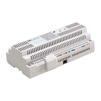
POWER SUPPLIER
XA/300LR
P
ower supply and control unit, with
ECHELON bus, enables standard and
residential system 300 installations to
be created.
Enables conversations between entry
p
anels, receivers and porter switch-
board.
It manages service controls (entry panel
self-connection/selection, door-lock
release, stair light, auxiliary control/por-
ter call) as well as the engaged status.
For data lines to the block’s entry
panels and/or main entrance panels,
the unit communicates by means of
the LON TALK protocol, whilst it uses a
BPT X2 TECHNOLOGY protocol
towards the receivers.
The bus connection towards the entry
panels consists of 3 twisted pairs plus
the power supply, whilst it uses a sin-
gle twisted pair plus power supply
towards the receivers.
The unit features a
CNV connector for
connection to the XAV/300 video
modulator and a
CNS connector for
connection to the ICB/300 selector.
The system 300 can be programmed
in either of two ways:
• Standard mode (installation with a
single XA/300LR power supplier) by
means of the actual XA/300LR sup
-
plier;
•
Extended mode (installation with a
number of XA/300LR power suppliers,
or if the standar
d configuration is to be
extended) by means of a PCS/300 or
MPP/300LR unit.
SYSTEM SETUP
WITH STANDARD MODE
PROGRAMMING
AND DEFAULT SETTINGS
System setup
1 - Maximum number of XA/300LR: 1.
2 - Maximum number of X2 blocks: 64.
3 - Maximum number of entry panels
per X2 block: 4.
4 - Maximum number of system 300
entry panels (19 with IPD/300LR).
5 - Maximum number of IPD/300LR
porter switchboar
ds: 1.
6 - Maximum number of users con
-
nected dir
ectly on XA/300LR: 100 (0 if
X2 blocks ar
e pr
esent).
7 - Maximum number of users for X2
block: 100 (99 with IPD/300LR porter
switchboar
d).
8 - Maximum number of IOD/303LR
r
elay actuators: 1.
Default settings
1 - System activation time: call 30 s,
conversation max 60 s.
2 - Door-lock release activation time:
-
for the system 300 entry panel (with
ICP/LR) with pushbuttons, time
options are: 1 s, 4 s, 8 s and 16 s;
- for the HAC/300LR entry panel: adju-
stable from 1 s to 255 s;
-
for the X2 entry panel: adjustable
from 1 s to 15 s;
3 - Aux. 1 control and door-lock relea-
se only enabled when receiver is cal-
led.
4 - Self-connection and switching
between entry panels for X2 block
panels only.
5 - First key on all system 300 and X2
entry panels allocated automatically as
p
orter call key.
SYSTEM FEATURES
W
ITH EXTENDED MODE
PROGRAMMING
In this mode, system features can be
extended to enable more complex,
flexible and customizable solutions.
Below are just some of the options:
-
extending the number of entry panels
and r
eceivers per block;
-
personalizzazione tempo di attivazio-
ne impianto e durata chiamata;
-
p
rogramming all receivers using a
pr
ogrammer (in this case, you will need
to collect the ID codes and enter them
in the tables that come with the pro-
gramming devices);
- texts can be customized for naming
entry panels and users.
STANDARD
PROGRAMMING
Programming structures the system by
allocating a unique identification code
to all LON units (for example, ICP/LR,
HAC/300LR, IPD/300LR) and X2 units
(for example, receivers and X2 block
entry panels such as HEV/301,
HEC/301, etc.).
Programming is divided into two parts:
- receivers programming
- entry panels and accessories pro-
gramming.
ENTERING AND EXITING
ST
ANDARD PROGRAMMING
T
o gain access to programming, it is
necessary to press the SERVICE but-
ton.
You can access programming by pro-
ceeding as follows.
1 - Programming receivers.
Press the SERVICE button for at least 3
s;
the yellow LED flashes at regular inter-
vals.
2 - Programming entry panels.
Press the SERVICE button again for
another 3 s;
the yellow LED stays on.
3 - Exiting programming and auto-
matic programming of IPD/300LR
and IOD/300LR units, where applica-
ble.
Lastly, press the SERVICE button for
approx. 1 s;
the yellow LED goes off.
PROGRAMMING
Power up the XA/300LR unit and pro-
ceed as follows.
WARNING. If the installation featu-
res more than one system 300
entry panel (ICP/LR o HAC/300LR),
or if you are dealing with an X2
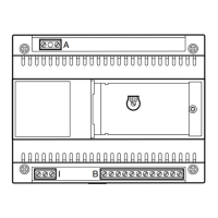
1
XA/300LR US
R4
03.2009/2407-2101
1
2
3
C
A
LED
SERVICE
CNV
B
CNS
L
A
B
+
−
+
−
SW2
RJ45
L
N
43,5
45
7,5
57
210
106
A
B
64,5
210
145
BPT S.p.A.
V
ia Cornia, 1
3
3079 Sesto al Reghena-PN-Italy
info@bpt.it – www.bpt.it
NOTE: This equipment has been tested and found to com-
ply with the limits for a Class B digital device, pursuant to Part
15 of the FCC Rules. These limits are designed to provide
reasonable protection against harmful interference in a residential instal-
lation.
T
his equipment generates, uses and can radiate radio frequency energy
and, if not installed and used in accordance with the instructions, may
cause harmful interference to radio communications. However, there is
no guarantee that interference will not occur in a particular installation.
If this equipment does cause harmful interference to radio or television
reception, which can be determined by turning the equipment off and
on, the user is encouraged to try to correct the interference by one or
more of the following measures:
- Reorient or relocate the receiving antenna.
-
Increase the separation between the equipment and receiver.
- Connect the equipment into an outlet on a circuit different from that to
which the receiver is connected.
- Consult the dealer or an experienced radio/TV technician for help.
EN
INSTALLATION
INSTRUCTIONS
DIMENSIONS IN MILLIMETRES
DIMENSIONES EN MILIMETROS