5
GB
INSTALLATION
INSTRUCTIONS
Attention.
Before installing the equipment, care-
fully read the “INSTALLATION WARN-
INGS” contained in the package.
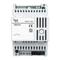
XA/301LR POWER SUPPLIER
Power supply and control unit, with
ECHELON bus, which makes it possible
to create System 300 systems, either
standard or residential type.
It allows conversation between entry
panel, internal extension and porter
switchboard.
It manages service controls (self-con-
nection/selection of entry panels, door
lockrelease,stairlight,auxiliarycontrol/
porter call) and busy status.
For data lines to main and/or block
entry panels, the unit communicates
using LON TALK protocol, while to inter-
nalextensionsituses BPT X2-X1TECH-
NOLOGY protocol.
The connection bus to entry panels is
composed of 3 twisted pairs plus power
supply if it is video, while if it is audio
connection is made by two twisted pairs
plus power supply. The connection bus to
internal extensions is composed of only
one twisted pair (System X1) or by a twist-
ed pair plus power supply (System X2).
The unit is equipped with a CNV con-
nector for connection to the XAV/300
video modulator and a CNS connector
for connection to the ICB/300 selector.
Compatibility with XA/300LR
Problems of incompatibility (such as
use of VSE/300 or use of EXEDRA type
internalextensions)canberesolvedby
changing the output voltage of Bus “B”
from 20 V DC to 18 V DC with poten-
tiometer P2.
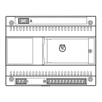
Function of terminals (fig. 1)
Terminal block A
~
Power supply input from mains
230 V AC 50/60 Hz
~
Terminal block B
L
LON data line
+
power supply output
entry panel18 V DC
–
A
Audio output from entry panel
Terminal board C
+XUP
Line X1
video entry control 20 V DC
B
–XUP
+
Centralized power supply output
for video entry control 18 V DC
–
Functional earth
Function of jumper SW2 (fig. 1)
Normally connected. Disconnect the
jumpertoachievemaximumsensitivity
of the line data receiver X2-X1.
Function of the yellow LED
- Regular flashing of the LED: internal
extensionprogrammingactive.
- LED on with brief interruptions: auto-
test mode active.
- LED on: programming of entry panels
active or malfunctioning.
- LED off: normal operation.
- LED flashing rapidly: short-circuit on
line X2 or on LON line.
Socket RJ45 (fig. 1)
This socket allows connection to the
programming device IPC/300LR or
IPC/301LR.
Technical characteristics
• Powersupply:230VAC50/60Hz.
The unit is electronically protected
against overloads and short circuits. In
addition, the two power supplies (18V
and 20V) have galvanic insulation.
• Electricalinput:120VA.
• Dissipatedpower:22Wmaxand8W
in stand-by.
• Powersupplyforentrypanelsand/or
internalextensionsofvideoentrycon-
trol X2 and accessories: 18V DC 2 A
(2.5 A peak).
• Powersupplyforentrypanelsand/or
internalextensionsofvideoentrycon-
trolX1andaccessories:18VDC1.2A
(1.7 A peak).
• Power supply of internal extensions
bybus:20VDC(terminalboardC).
• The unit XA/301LR can power by
itself:
- 1 TM-series video entry panel, ana-
logue or digital Targha series;
- 1videoentrycontrolinternalextension
X1 or X2 active and 63 in standby;
- 5 amplifiers XDV/300A;
or
- 2 video entry panels, analogue or
digital Targha series;
• Number of users that can be con-
nectedonthelineX2-X1(B):
- 100 video entry controls;
- 200 audio entry controls.
• Internal extensions that can be acti-
vated with the same call: 3 (8 with
atleast6extensionswithattenuated
note).
• Operating temperature: from 0 °C to
+35 °C.
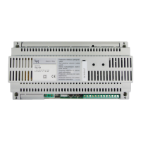
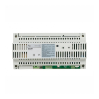
• Dimensions:low-profile12-unitmod-
ule for installation on DIN rail (fig. 2).
Instructions for installation
ATTENTION.
The power supplier must always
be installed horizontal (provide for
suitable ventilation if the unit is
installed in an enclosure).
The unit may be wall-mounted using
the DIN rail provided, applying the pro-
tective terminal covers (fig. 3-4). The unit
may be installed in an electrical panel
on DIN rail (EN 50022) (fig. 5).
For disassembly, proceed as shown in
figure 6.
For dimensions, see figures 2-A and 2-B.
GENERAL INFORMATION ON
PROGRAMMING
Programming of the System 300 can be
carriedoutintwoways:
• Programminginexpandedmode
To be carried out with a PC and soft-
ware PCS/300 in systems with several
XA/301LR power suppliers or if you want
toexpandthebasicconfiguration.
• Programminginbasicmode
To be carried out through XA/301LR
power supplier in systems equipped
with only one power supplier.
Characteristics of a system pro-
grammed in expanded mode
Inthisway,itispossibletoexpandallof
the characteristics of the system, allow-
ingforsolutionsthataremorecomplex,
flexibleandcustomizable.
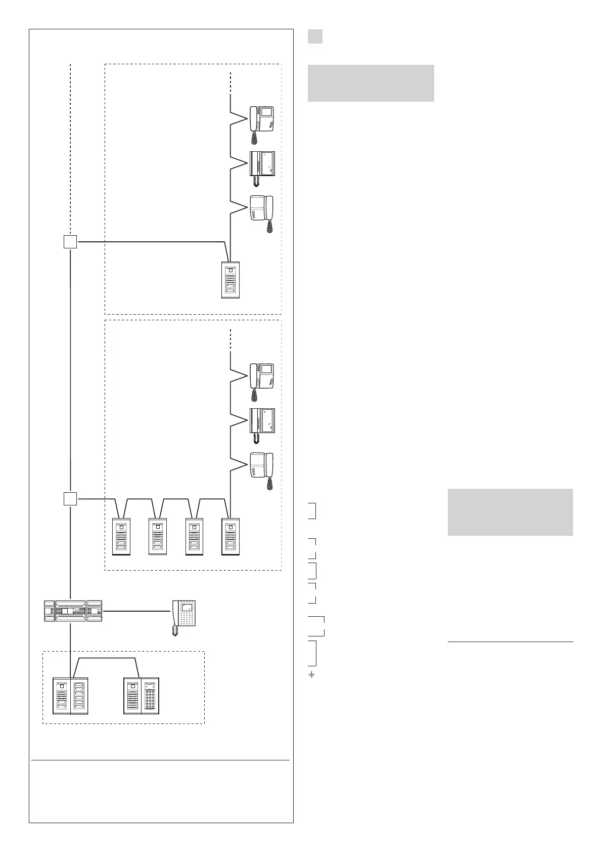
7
HPV/1+
HAV/200+
HIA/300+
ICP/LR+
...HEP/306+
...HTS
HPV/1+
HAV/200+
HIA/300+
HAC/300LR+
2HTS
XA/301LR
Master
Slave
Slave
Slave
ICB/300
IPD/300LR
XAV/300
Master
1
2
3
4
5
6
9
8
7
0
C
T
SP
Slave and master block entry panels:
HEV/301, HEC/301, HET/301, AZV/304, AZ/304.
Block no. 2
X2-X1
Block no. 1
X2-X1
Switchboard
300 entry panels
RESIDENTIALSYSTEMWITHBLOCKSX2-X1
Entry
panel
of block
X2-X1
Entry
panels
of block
X2-X1
 Loading...