MAINTENANCE
ROTARY CUTTERS
L
L
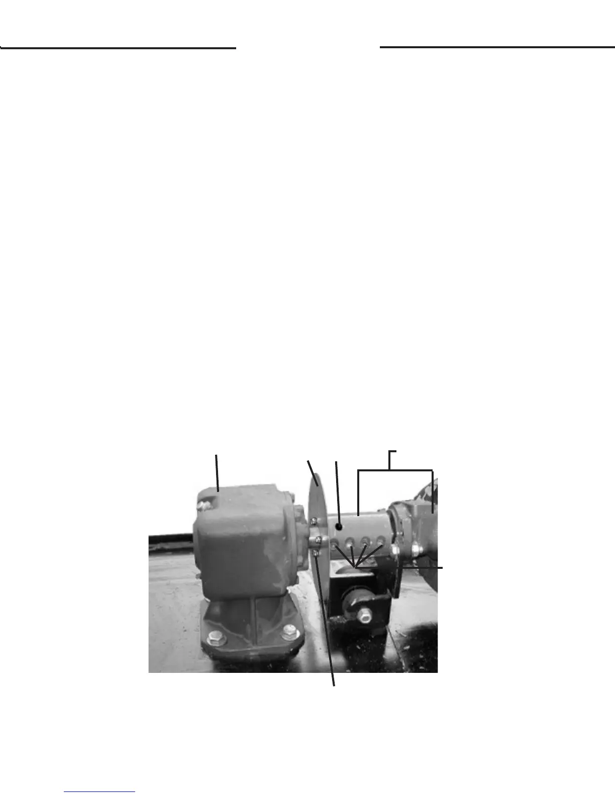
2. Remove the roll pin holding the coupler to the gearbox and the three cap-
screws holding the blade rotation indicator to coupler.
3. Loosen the four socket head capscrews on the coupler and slide the cou-
pler along with the motor assembly off of the gearbox drive shaft.
4. Remove the four capscrews securing the gearbox to the rotary cutter
deck, and lift the gearbox off the cutter.
5. Install the new gearbox with the existing hardware removed in Step #4.
6. Position the stump jumper onto the lower end of the gearbox and reinstall
the castle nut. Torque nut to 230 ft. lbs. Continue to tighten until the next
nut castellation aligns with cross pin hole in the output shaft. Final torque
range must be between 240 - 250 lt. lbs. Reinstall cotter pin.
7. Install the blade rotation indicator onto the gearbox followed by the cou-
pler/motor assembly.
8. Reinstall the .25" capscrews securing the blade rotation indicator to the
coupler, reinstall the roll pin, and tighten the four sockethead capscrews
specication. See Section O.
9. Check lubrication level in the gearbox and add as needed. See Section H.
9017 10-11-06-4
ROLL
PIN
SOCKETHEAD
CAPSCREWS
GEARBOX
BLADE
ROTATION
INDICATOR
.25" UNC X .50" CAPSCREWS
.25" LOCK WASHERS
REMOVE COUPLER AND
MOTOR ASSEMBLY
TOGETHER
STANDARD FLOW
CUTTER SHOWN