MAINTENANCE
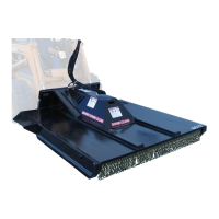
ROTARY CUTTERS
L
L
9016
11-3-04-2
WARNING! Avoid serious injury. Lower the rotary cutter to the ground, set
the parking brake, stop the skid-steer engine and remove the
key before leaving the operator's seat. If unit must be left
raised for maintenance, block the unit securely to prevent
accidental release of the lifting mechanism. Disconnect the
hydraulic couplers.
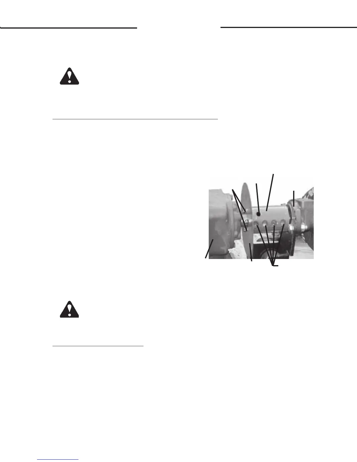
REPLACING GEARBOX/MOTOR COUPLER
When replacing the coupler the unit should be setting on the ground with
the hydraulic couplers disconnected.
1. With unit setting on the ground and hydraulic couplers disconnected,
loosen the four sockethead capscrews on the coupler and remove the
motor with the motor mounting plate still installed.
2. Remove the roll pin holding the
coupler to the gearbox, and the three
capscrews holding the blade rotation
indicator to coupler.
3. Replace the coupler on the gearbox
shaft, and reinstall the roll pin and the
blade rotation indicator using the
existing hardware.
4. Reinstall the motor into the coupler,
and retighten the sockethead cap-
screws. Torque to specification.
See Section O.
COUPLER
ROLL
PIN
SOCKETHEAD
CAPSCREWS
GEARBOX
BLADE
ROTATION
INDICATOR
.25" UNC X .50"
CAPSCREWS
HYDRAULIC
MOTOR
WARNING! Avoid serious injury. Lower the rotary cutter to the ground, set the
parking brake, stop the skid-steer engine, and remove the key
before leaving the operator's seat. If unit must be left raised for
maintenance, block the unit securely to prevent accidental release
of the lifting mechanism. Disconnect the hydraulic couplers.
REPLACING GEARBOX
When replacing the gearbox, the unit must be blocked securely off the ground
to gain access to the castle nut holding the stump jumper to the lower end of the
gearbox.
1. With unit securely blocked off the ground and hydraulic couplers discon-
nected, remove the cotter pin and castle nut holding the stump jumper to
the lower end of the gearbox. NOTE: Be prepared for the weight of the
stump jumper with the blades attached to fall when the castle nut is
removed.